Before I get into more details about how it was build, take a look at this overview video.
- to be able to make double sided PCBs
- have a display to indicate exposure time
- a way to set exposure time quickly using buttons or rotary encoder and a way to reset the timer
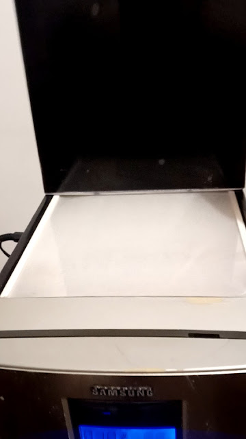
The front sliding panel could be replaced with a small door. When the front panel is raised we can see the following things:
1. is a fix transparent panel on which the PCB sits
2. two sheets of transparent plastic with nuts and bolts on each corner used to press the mask on the PCB. The nuts are melted into the plastic. This is a glass like plastic and is very cheap.
3. a panel made out of wood on which UV LED strips are glued. Under the fixed panel (1) is another such panel for exposing the bottom side of the PCB.
There are also two PCBs with some artwork etched on them that covers the part where the electronic control board is located.
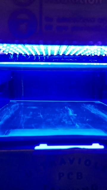
Through the fixed transparent panel (1) the bottom UV LED strips can be seen.
On the top is another little compartment used for aligning the masks. I've used red LED strips but then I realized the white ones are preferred because they are not ON while working with photo sensitive things. I have used PWM to control their brightness but even so they are too bright to work with. I believe 4 strips of LEDs would be enough. A cover is used to protect it from dust.
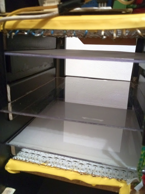
Starting from the top, there is a transparent plastic panel and 5 cm beneath it is a cardboard panel on which white LED strips can be mounted. Below this is the electronic board that sits on a wood panel. Beneath this wood panel are glued the UV LED strips that expose the top side of the PCB.
The inner width of the box is 18 cm and was set by the front panel size, but it could be bigger for making larger PCBs. The box depth is 20 cm but the panels are recessed 1 cm from the back to allow the air flow.
The top panel is 5 cm higher than the fixed panel but to this distance should be added the width of 3 plastic panels plus the nuts beneath them. Why 3 panels? In the image are only two but I noticed that the top side is a bit overexposed compared to the bottom side, since on the bottom side are two plastic sheets in front of the LEDs and on the top only one. So is better to add another plastic sheet on that mobile vice.
UPDATE 1:
This worked good with pre-sensetized boards where the exposure time was about 4 minutes but with photo sensitive dry film the exposure time would have to be 25 seconds. This leads to light bleed between the mask traces.
Solution: the distance from the LEDs must be greater because the further the light source is the sharper the shadow. Also the light must be diffused using. I've tried with two layers of tracing paper over the LEDs and the results were better even if the exposure time will increase a bit. The paper could be glued on some sheet of plastic and placed about 1 cm over the LEDs so the individual LEDs can not be seen.
Initially I covered the inner walls with aluminum foil but then I realized it was not a good idea because light rays from the sides are not wanted. So I highly recommend black paper for inner sides.
Below this is a ATX power supply.
On the back top side is mounted a PC fan that draws air from the top side to prevent the LEDs from overheating.
Wavelength: 395 - 405nm.
The width of a LED strip is 1cm so for 18cm wide panel 18 LED strips are needed with 20cm length which equals 360 cm or 3.6 m of tape needed. Multiply this by two for the other side. So two roles of 5m are more than enough.
Avoid staring at the UV light because that could damage the eyes and skin.
For controlling the LEDs I've used a relay for each side (top and bottom) because I like the clicking sound.
If you have any questions, leave them in the comment section below.
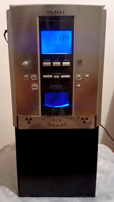
UV Box Requirements:
- the width of the box must be calculated to fit your widest PCB you plan to make. Same for the depth.- to be able to make double sided PCBs
- have a display to indicate exposure time
- a way to set exposure time quickly using buttons or rotary encoder and a way to reset the timer
Box Dimensions and Construction:
![]() |
Front side |
The front sliding panel could be replaced with a small door. When the front panel is raised we can see the following things:
1. is a fix transparent panel on which the PCB sits
2. two sheets of transparent plastic with nuts and bolts on each corner used to press the mask on the PCB. The nuts are melted into the plastic. This is a glass like plastic and is very cheap.
3. a panel made out of wood on which UV LED strips are glued. Under the fixed panel (1) is another such panel for exposing the bottom side of the PCB.
There are also two PCBs with some artwork etched on them that covers the part where the electronic control board is located.
Through the fixed transparent panel (1) the bottom UV LED strips can be seen.
![]() |
Top side |
![]() |
Way too many LEDs |
![]() |
View from the back |
The inner width of the box is 18 cm and was set by the front panel size, but it could be bigger for making larger PCBs. The box depth is 20 cm but the panels are recessed 1 cm from the back to allow the air flow.
The top panel is 5 cm higher than the fixed panel but to this distance should be added the width of 3 plastic panels plus the nuts beneath them. Why 3 panels? In the image are only two but I noticed that the top side is a bit overexposed compared to the bottom side, since on the bottom side are two plastic sheets in front of the LEDs and on the top only one. So is better to add another plastic sheet on that mobile vice.
UPDATE 1:
This worked good with pre-sensetized boards where the exposure time was about 4 minutes but with photo sensitive dry film the exposure time would have to be 25 seconds. This leads to light bleed between the mask traces.
Solution: the distance from the LEDs must be greater because the further the light source is the sharper the shadow. Also the light must be diffused using. I've tried with two layers of tracing paper over the LEDs and the results were better even if the exposure time will increase a bit. The paper could be glued on some sheet of plastic and placed about 1 cm over the LEDs so the individual LEDs can not be seen.
Initially I covered the inner walls with aluminum foil but then I realized it was not a good idea because light rays from the sides are not wanted. So I highly recommend black paper for inner sides.
Below this is a ATX power supply.
On the back top side is mounted a PC fan that draws air from the top side to prevent the LEDs from overheating.
Electric part:
Ultraviolet LED strip is a 5050 UV SMD LED strip with 60 leds/m powered by 12V.Wavelength: 395 - 405nm.
The width of a LED strip is 1cm so for 18cm wide panel 18 LED strips are needed with 20cm length which equals 360 cm or 3.6 m of tape needed. Multiply this by two for the other side. So two roles of 5m are more than enough.
Avoid staring at the UV light because that could damage the eyes and skin.
For controlling the LEDs I've used a relay for each side (top and bottom) because I like the clicking sound.
If you have any questions, leave them in the comment section below.
No comments:
Post a Comment