Thursday, February 1, 2018

How to build your own USB to UART serial converter using FT232 with voltage level shifting

The board includes 500mA fuse protection, EMI filtering, power LED indicator, RX and TX LED indicators, and a voltage level shifter that makes it compatible with 3.3V and 5V boards. This way you don't need to check the jumper if it outputs 5 or 3.3V so you don't risk burning your microcontroller. It works with both voltages.

Update: 2024, March, 6: I made another serial adapter build around FT231 which require less components since it is 5V tolerant and is also cheaper. It is part of a development board: https://www.programming-electronics-diy.xyz/2023/06/breadboard-development-board-for-avr.html#USB_Interface.


USB to UART serial converter board tutorial DIY home build


Wednesday, January 24, 2018

EAGLE CAD Tips | How to Add Custom Image Logo to Your PCB

Adding a custom image logo to your PCB can make your project look more professional. In the following video I will demonstrate how you can quick and easy import an image in Eagle CAD and place it on your PCB. You can place graphics on copper layers to be etched or on silkscreen to be printed.

In this video I show as an example a USB to UART board. Eagle expects a Bitmap image with less than 256 color depth.The text image was made in Inkscape and since Inkscape can't export Bitmap (.bmp), I exported the image as PNG, then using IrfanView I lowered the color depth to 2 colors and saved as Bitmap.


Saturday, October 28, 2017

How to use A4988 stepper motor driver module tutorial

A4988 stepper motor driver module

This driver can be used to easily control a bipolar stepper motor or a uni-polar stepper connected in a bipolar mode. Can output up to 2A per phase (with a heatsink) and works with motor voltages from 8 to 35 volts.

  • Simple step and direction control interface
  • Five different step resolutions: full-step, half-step, quarter-step, eighth-step, and sixteenth-step
  • Adjustable current control lets you set the maximum current output with a potentiometer, which lets you use voltages above your stepper motor’s rated voltage to achieve higher step rates
  • Intelligent chopping control that automatically selects the correct current decay mode (fast decay or slow decay)
  • Over-temperature thermal shutdown, under-voltage lockout, and crossover-current protection
  • Short-to-ground and shorted-load protection

A4988 and Nema17

Library for A4988 stepper motor driver using timer interrupt

Update 4, October, 2023: I have made a new library for controlling stepper motor drivers that supports multiple motors and has a better acceleration algorithm. It can also coordinate xyz steppers.

This library is designed for AVR ATmega328 microcontroller, but with few adjustments can work with any AVR microcontroller with at least 3-4 Kb of flash program memory.
At the moment only one motor is supported.

Features

  • the interrupt can be triggered by Timer0 or Timer1
  • automatic microstepping mode selection
  • can work with constant and very low speeds
  • accelerated speed mode, with separate acceleration and deceleration settings
  • can work with only one pin of the microcontroller if the rest are hardwired

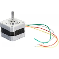
Nema 17 Bipolar Stepper Motor

Characteristics:


Features
Program Memory
Data Memory (SRAM)
All enabled
3552 bytes
40 bytes
Acceleration, no microstepping
3088 bytes
40 bytes
Microstepping, no acceleration
2104 bytes
14 bytes
No microstepping, no acceleration
1724 bytes
12 bytes

Compiled using avr-gcc (WinAVR 20100110) 4.3.3 and -Os optimization level and MATH_LIB = -lm.
If MATH_LIB = -lm is commented out in Make file, the memory with all functions enabled is 6520 bytes program and 304 bytes data memory.So allways uncomment MATH_LIB = -lm.


Saturday, June 24, 2017

Homemade Cheap ESD Safe Electronics Storage Box

Storing and finding electronic components can be a pain. I tried many solutions over the years until I found a solution that suits my needs - making boxes from 2mm plastic sheets. The cost is very low and can be made in whatever sizes you need.

Electronics storage box diy 1

Thursday, June 8, 2017

Salvage a VFD from a broken DVD

I had a broken DVD Player Philips DVP5960 so I thought to use the display with my other projects. The display is a Vacuum Fluorescent Display or VFD for short. This VFD is mounted on a front board alongside with an IR receiver and 4 tactile buttons and it is controlled by the ET16312N driver chip. You can use this front board for a digital clock or anything else that needs a display and a few buttons. The buttons can be desoldered and positioned elsewhere extended by wires.

To  create all this circuitry from scratch would be difficult. The ET16312N driver needs +5V, +12V and -24V. Also you would need to create an AC signal, multiplex the grids, drive the anodes, etc. but all this is already build for oyu on the front board. The power supply from the DVD Player can be used but I want to power the VFD from batteries so I will try to make a power supply myself.
The weird thing is that on the 12V line the VFD driver draws about 53 mA even if the display is off or dimmed. On -24V it draws about 6 mA. So yeah, it is not well suited for batteries unless you physically turn of the power using a transistor controlled by the MCU when the display is in standby.


Philips DVP5960 Front Board together with Crapduino

Saturday, June 3, 2017

Library for interfacing AVR microcontrollers with ET16312N VFD (Vacuum Fluorescent Display) driver

I had a broken Philips DVP5960 DVD player and I thought it's a good idea to salvage and use the VFD display in some project. And so this code was born.


Vacuum Fluorescent Display (VFD) from a DVD Player controlled by AVR MCU

To know more about the communication protocol between the microcontroller and the VFD driver chip, visit this post Salvage a VFD from a broken DVD.