Monday, January 18, 2021

7 segment display library for AVR microcontrollers | ATmega328P

There are many ways to control a seven segment display - using a dedicated IC or shift registers which are preferred because they don't require many pins. However this library is made for when you have the segments driven directly from microcontroller pins and each digit is controlled using a transistor.

You have the option of padding the numbers with zeros and displaying them at a certain position, useful for making digital clocks.

To see this library used in a real project, check out this video Digital Clock With RGB Night Lamp & Spherical Shelf.

Seven segment display library for AVR microcontrollers

What is a 7-segment display

As the name suggests it is a display that is made up of 7 segments. Each segment is simply an LED. Including the dot there are actually 8 LEDs and this fits perfectly on an 8-bit microcontroller's port. This display is mainly made for numerical values but some alphabetical characters can be displayed as well.

Types of 7 segment displays

There are two types of seven segment displays - common cathode and common anode. Common cathode displays have all the ground sides (cathodes) of the LEDs connected together while common anode displays have all the positive sides (anodes) of LEDs tied together.

The 7 segment display can have from 1 up to 6 or 8 digits. One digit can display numbers from 0 to 9 and a dot for numbers with decimals. On 4 digit seven segment display the maximum number that can be displayed is 9999.

7 segment display internal equivalent circuit OPD-Q5621LE-BW
Figure 1: Internal equivalent circuit of a 7 segment display from OPD-Q5621LE-BW datasheet


Saturday, January 16, 2021

Read and debounce multiple buttons using interrupt on AVR microcontrollers

This library provides an easy way for reading and debouncing one or multiple buttons connected to a microcontroller. Apart from basic functionality, the library provides some extra functions such as reading a combination of buttons, and detecting a button long press or a double pressed button. These are especially useful in a low button count system.

Multiple buttons can also be read by a single ADC pin.


Button debouncing library for AVR microcontrollers

Contents


What is button debouncing

Saturday, January 9, 2021

millis and micros library for AVR microcontrollers - milliseconds and microseconds time tracking

Having precise timing in microcontrollers is important in many projects. For this you can use the two libraries presented in this article - millis & micros.

millis library triggers a timer interrupt every 1 millisecond and increments the milliseconds variable. The user can select the size of the milliseconds variable ranging from char (8 bits) to long long (64 bits) with an overflow from 255 milliseconds to 584.9 million years.

micros library is almost the same as millis but for microseconds. The overflow is between 255 microseconds and 584942 years.

For both libraries the user can select which timer to use: Timer0, Timer1, Timer2, Timer3 or Timer4.

In the case of millis library, it is recommended that other interrupts take less than 1 millisecond to complete otherwise the millis timer interrupt will be delayed. For the micros the ISRs must finish in less than 100 microseconds. The faster the CPU clock the better.

For the milliseconds and microseconds variable decide if you really need a 32 or 64 variable (long and long long) because the bigger the variable the longer it takes to increment it. For example on a 1MHz CPU it takes about 77 microseconds to increment a long long variable.

millis & micros library for AVR microcontrollers


Thursday, January 7, 2021

ISP programming rig for microcontrollers

I had to program many types of microcontrollers over the years and so I was thinking why not build a simple programming rig to make things easier. This rig is for the In-system programming (ISP) method and not for the UART method.

How to easily upload the code to any microcontrollers using ISP rig

The board in the above image is not the programming rig but a digital clock shown as an example. Notice the 6 pin header near the cap. The pins are not soldered through hole but on SMD pads. This way it can be easily de-soldered after finishing the project and on some space constrained projects this is a must.

Monday, November 9, 2020

Constant current LED driver using ATtiny13 - Headlamp flashlight

Here is a simple constant current source for driving 7 white 5mm LEDs and also 2 red LEDs. I have made the circuit for a headlamp flashlight that had a soft button which required a microcontroller. To save the battery life the microcontroller is powering down when the lights are off with a current draw of only 0.3uA.

Constant current LED driver using ATtiny13 - Headlamp flashlight

Thursday, October 15, 2020

Capacitive transformerless power supply schematic for PIR motion sensor NV-1111.35

In the previous article I have explained how a PIR motion sensor works. There you can also find the schematic for the NV-1111.35 PIR sensor which is based on a popular three stage op-amp topology. Understanding this can help you understand other pyroelectric sensors as well.

This sensor is powered by a capacitive transformerless power supply with an output of 8V and 7mA of current.

Capacitive power supply for pyroelectric (PIR) sensors

Sunday, October 11, 2020

How an outdoor motion PIR sensor switch works with schematic

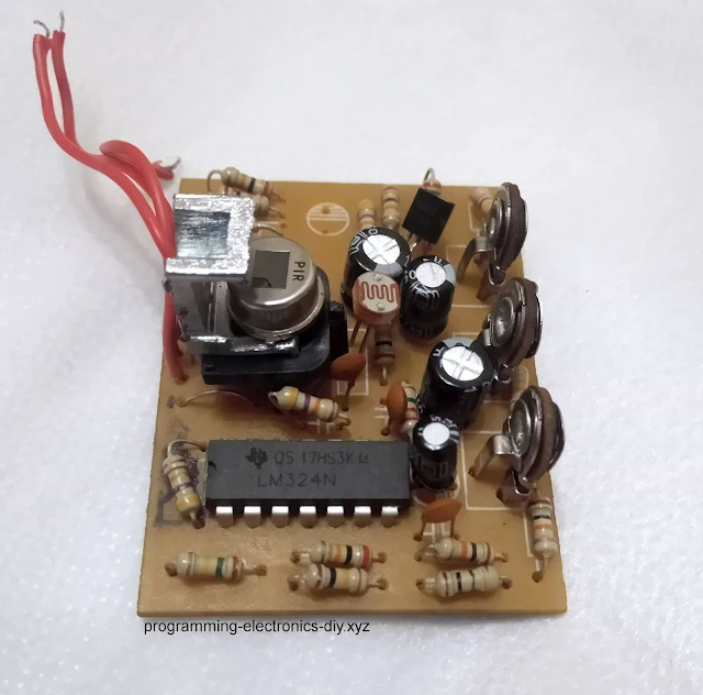
In this article I will be explaining how a pyroelectric (PIR) sensor works and show the reverse engineered schematic simulated in LTspice. The schematic is for NV-1111.35 outdoor PIR sensor used to switch a mains light and has 3 potentiometers for setting SENSITIVITY, LUX and TIMEOUT.

This sensor is based on a popular three stage op-amp topology. Understanding this can help you understand other pyroelectric sensors as well and also something about active filters using LM324 and removing and setting a DC voltage bias.

Outdoor PIR sensor board repair

Outdoor PIR sensor board repair