Thursday, July 7, 2022

SD Memory Card Library for AVR Microcontrollers - SD and FAT Driver

This is a library for reading and writing of SD flash memory cards using FAT16 or FAT32 file systems, over the SPI protocol, and is designed with embedded systems in mind. It includes an SD card driver that uses the SPI interface and a FAT driver that is controlled by the host microcontroller.

There are two main standards for flash memory cards: MMC (MultiMediaCards) and SD (Secure Digital), SD being the most used today. SD was developed by the SD Association (SDA) as an improvement over MMCs. These cards have basically a flash memory array and a microcontroller inside that controls erasing, reading, writing, error controls, and wear leveling of the flash array. The data is transferred between the memory card and the host controller as data blocks in units of 512 bytes.

The recommended file systems for memory cards are FAT12/16/32 or exFAT. Maximum volume sizes for each one are: 256MB, 4GB, 16TB* for FAT32 and 128PB for exFAT.

*Windows will refuse to format cards over 32GB using FAT32, offering exFAT and NTFS as an option but there are workarounds and third-party software that can do that.


FAT16 FAT32

Flash RAM Flash RAM
Read 6.1k 605 6.6k 607
Write 7.8k 607 8.6k 609
Read/Write 7.9k 607 8.7k 609

Some rounded up values of the code footprint depending on the functions used: for reading, writing or both. RAM size is expressed in bytes and it includes 512 bytes for the read/write buffer.

Features

  • Communication protocol: SPI
  • Supported memory cards: SD cards (MMC's are not implemented)
  • Includes SD driver: Yes
  • Supported file systems: FAT16 and FAT32
  • Support for LFN (Long File Names): Yes (up to 255 characters)
  • Formatting utility: No
  • Multiple files and folders instances: Yes
  • Ability to create folders and directories
  • Delete files: Yes, with recursive removal of files and sub-directories
  • FSInfo (FAT32): not implemented in order to reduce the code size. The only situations when this could be a downside is when querying for free space, creating files/folders or expand them since this is when it is necessary to search for a free cluster. If the card is mostly empty, even if it has a large capacity, the search for a free cluster will be very quick. As the card is filled it will take longer (few seconds).
 

Contents

  1. SD Card Pins
  2. Schematic Interface
  3. Return Values
  4. File Object Structures
  5. File names
  6. The Buffer, the Writing and the Flush
  7. Code Examples
  8. Library Configuration
  9. Library Usage
    1. Volume Management
      1. Card Detect
      2. Card Initialization
      3. Volume Free Space
      4. Volume Capacity
      5. Read Volume Label and Serial Number
    2. Directory Access
      1. Make Directory
      2. Open Directory
      3. Open a Directory by Index
      4. Go Back
      5. Find by Index
      6. Find Next
      7. Count Items
    3. File Access
      1. Make File
      2. Delete File or Folder by Index
      3. Delete File or Folder by Name
      4. Open File
      5. Open File by Index
      6. Set File Pointer
      7. Seek File End
      8. Get File Pointer
      9. Write Float Number
      10. Write Number
      11. Write String
      12. Write File
      13. Truncate File
      14. Flush Data
      15. Read File
      16. End of File Check
      17. Error Flag Check
      18. Clear Error Flag
      19. Get Filename
      20. Get Index
      21. Get File Size
      22. Get Write Date and Time
      23. Get File Attributes
      24. Setting File Date and Time
  10. Download SD Card Library

SD Card Pinout

Both MMC/SD standards have their own proprietary protocols but they also support SPI which can be selected during card initialization. Since microcontrollers have SPI integrated hardware, this is the most used interface for memory cards.
Thursday, May 12, 2022

Displaying Bitmap images on ST7735 display from a memory card using an AVR microcontroller

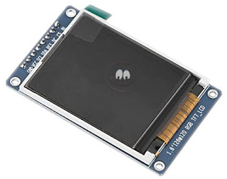
This is an extension for the ST7735 display driver library made for displaying Bitmap images stored on an SD memory card on the ST7735 TFT display using an AVR microcontroller. The Bitmaps can be of 16-bit or 24-bit colors. Since the ST7735 display driver only accepts 16-bit colors, the 24-bit images will be converted to 16-bits.

Here is a short demo video:


The images must be resized first to fit the size of your display. A free and popular software for this task is Irfanview. Open the image using Irfanview then press CTRL+R, specify the new image size then save it as a .bmp and place the images on the memory card in a folder of your choice.

Saturday, February 5, 2022

Library for ST7735 TFT display driver for AVR microcontrollers

There are already some libraries for the ST7735 display driver such as the one from Adafruit but made only for Arduino. I needed one for AVR microcontrollers in general, so I made this one. With a bit of twiking it could also be adapted to work with other types of microcontrollers. This library is based on the one from Adafruit but with some functions removed, modified and others added. The interface needs 4 microcontroller pins and it uses SPI for communication.

Library for the ST7735 TFT display driver for AVR microcontrollers

Library for the ST7735 TFT display driver for AVR microcontrollers demo

There are many GUI elements that can be created and above are a few examples such as: selectable menus, scrollbars, check-boxes and animated icons. I made those in Inkscape for a battery charger project.

Contents:


Wiring the ST7735 TFT display

It is important to note that the power supply voltage for the ST7735 display driver is maximum 3.3V and same for the other input pins. Some TFT modules include a 3.3V regulator and a voltage level shifter in which case it can be used with 5V microcontrollers, if not some level shifting must be done if the microcontroller is not powered from 3.3V.

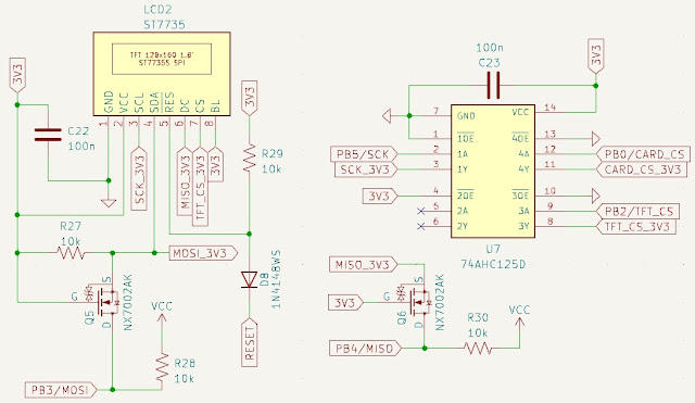
ST7735 connection diagram with voltage level shifter

This schematic is an example that also includes an SD card. Here, MISO is used for DC pin (Data/Command) since the ST7735 doesn't use the MISO in the 1-Wire SPI protocol, and also as MISO (Master In Slave Out) for the SD card. The 74AHC125D can't be used for this pin since is not bi-directional, hence the mosfet level shifter.

ST7735 connection diagram with voltage level shifters and pinout

1 - GND - ground power supply

2 - VCC - 3.3V power supply (minimum 150mA)

3 - SCL - SPI serial clock pin (SCK)

4 - SDA - SPI serial data input/output (MOSI)

Tuesday, November 9, 2021

Mains short circuit protection, current limiter using incandescent light bulb in series

This is a short circuit protection unit that will limit the current when working with mains voltage in case of a short circuit. It is useful for testing repaired equipment and can also be used to test transformers and light bulbs as a bonus. If a short circuit would to occur all that will happen would be to light up the incandescent light bulb thus protecting the equipment and household wiring.

Mains short circuit protection and current limiter using tungsten lamps in series

How to build a mains short circuit protection unit for testing and repairing electrical equipment and transformers

The working principle of this unit is very simple - an incandescent tungsten light bulb is placed in series with the load. If the current draw by the load is small comparative to the bulb's power, the light bulb will not glow and it's resistance will be low. In case of a short circuit the higher current draw will cause the light bulb to heat up and glow and that will increase the resistance of the tungsten filament therefore limiting the current.

When cold the incandescent tungsten filament has a low resistance (~25-50 ohms for a 75W bulb). When mains power is applied to it the filament will get glowing hot and the hotter a metal is the more agitated the electrons are, bouncing everywhere, and so creating the effect of a higher resistance when hot versus when cold.

Friday, October 22, 2021

DAC library for MCP4706, MCP4716, MCP4726 and AVR microcontrollers

This library is intended for the MCP47x6 series of DAC devices that includes MCP4706 (8-bit DAC), MCP4716 (10-bit DAC) and MCP4726 (12-bit DAC).

DAC library for MCP4706, MCP4716, MCP4726 and AVR microcontrollers

Table of Contents


MCP47x6 DAC pinout

MCP47x6 DAC pinout

1 - VOUT: this is the DAC analog output voltage. In Normal mode, the DC impedance of the output pin is about 1Ω. In Power-Down mode, the output pin is internally connected to a known pull-down resistor of 1 kΩ, 125 kΩ, or 640 kΩ. The VOUT pin can drive up to 100 pF of capacitive load in parallel with a 5 kΩ resistive load. It is recommended to use a load with RL greater than 5 kΩ. Driving large capacitive loads can cause stability problems for voltage feedback op amps.

Tuesday, October 19, 2021

I2C and TWI (Two Wire Interface) library for AVR microcontrollers

In the last article I talked about How I2C and TWI protocol works and we saw that they are mostly the same so this library works for both I2C and TWI serial interfaces. You don't have to know every detail about how the I2C protocol works but I strongly recommend reading the article to have a general idea about it, and that way it will be easier to use this library.


Using the I2C, TWI library with an AVR microcontroller

Setting the library file

As always, first include the library file:

#include "twi.h"

Most AVR microcontrollers have two TWI modules TWI0 and TWI1 so to choose between the two there is the following line of code:

#define TWI_MODULE_NUMBER	0 // TWI module 0 or 1

The default module is TWI0.

Functions


void TWI_Init(uint32_t frequency)

Used to initialize the TWI module. This will set the TWI bit rate and enable global  interrupts. 400kHz is the maximum TWI speed that regular AVR microcontrollers supports although I have managed to talk to a DAC at 577kHz.

frequency:  can be one of the following constants or any value between 100-400kHz.

#define TWI_400KHZ	400000 // Hz
#define TWI_100KHZ	100000 // Hz

Saturday, October 16, 2021

How the I2C and TWI (Two Wire Interface) protocol works

I2C is a two-wire serial bus communication protocol invented by Phillips in 1982. TWI stands for Two Wire Interface and, for the most part, this bus is identical to I²C. The name TWI was introduced by Atmel and other companies to avoid conflicts with trademark issues related to I²C. Because these two protocols are almost the same I will refer to them interchangeably throughout the course of this article.

This protocol is very used nowadays by all sorts of devices such as DACs, LCDs, sensors, etc. so it's worth learning about it.

As a disclaimer I need to mention that most parts of this article contains fragments from the ATmega328, 324 datasheet and MCP4706 datasheet. I liked how they explained the I2C, TWI protocol  and since not many people read the datasheets I want to share this information with anyone interested in the TWI protocol.

If you're interested in a I2C, TWI library it can be found at this link I2C, TWI library.

Features

  • 7-bit Address Space Allows up to 128 Different Slave Addresses
  • Multi-master Arbitration Support
  • General call addressing

The I2C interface specifies different communication bit rates. These are referred to as Standard, Fast or HighSpeed modes.

  • Standard mode: bit rates up to 100 kbit/s
  • Fast mode: bit rates up to 400 kbit/s
  • High-Speed mode (HS mode): bit rates up to 3.4 Mbit/s

High-Speed mode is currently unsupported by the TWI.

Table of Contents


Two-Wire Serial Interface Bus

The TWI protocol is able to interconnect up to 128 different devices using only two bidirectional bus lines: one for clock (SCL) and one for data (SDA). The only external hardware needed to implement the bus is a single pull-up resistor for each of the TWI bus lines. All devices connected to the bus have individual addresses, and mechanisms for resolving bus contention are inherent in the TWI protocol.

TWI Bus Interconnection

The number of devices that can be connected to the bus is only limited by the bus capacitance limit of 400pF and the 7-bit slave address space. The SCL and SDA pins are open-drain configurations. For this reason these pins require a pull-up resistor.