Showing posts with label Microcontroller AVR. Show all posts

Saturday, January 9, 2021

millis and micros library for AVR microcontrollers - milliseconds and microseconds time tracking

Having precise timing in microcontrollers is important in many projects. For this you can use the two libraries presented in this article - millis & micros.

millis library triggers a timer interrupt every 1 millisecond and increments the milliseconds variable. The user can select the size of the milliseconds variable ranging from char (8 bits) to long long (64 bits) with an overflow from 255 milliseconds to 584.9 million years.

micros library is almost the same as millis but for microseconds. The overflow is between 255 microseconds and 584942 years.

For both libraries the user can select which timer to use: Timer0, Timer1, Timer2, Timer3 or Timer4.

In the case of millis library, it is recommended that other interrupts take less than 1 millisecond to complete otherwise the millis timer interrupt will be delayed. For the micros the ISRs must finish in less than 100 microseconds. The faster the CPU clock the better.

For the milliseconds and microseconds variable decide if you really need a 32 or 64 variable (long and long long) because the bigger the variable the longer it takes to increment it. For example on a 1MHz CPU it takes about 77 microseconds to increment a long long variable.

millis & micros library for AVR microcontrollers


Monday, November 9, 2020

Constant current LED driver using ATtiny13 - Headlamp flashlight

Here is a simple constant current source for driving 7 white 5mm LEDs and also 2 red LEDs. I have made the circuit for a headlamp flashlight that had a soft button which required a microcontroller. To save the battery life the microcontroller is powering down when the lights are off with a current draw of only 0.3uA.

Constant current LED driver using ATtiny13 - Headlamp flashlight

Monday, September 28, 2020

Using USBTinyISP programmer with Atmel Studio 7 | AVR programming

In the last article I talked about Programming any AVR microcontrollers using WinAVR and USBTinyISP but recently I found that USBTinyISP can be easily used together with Microchip Studio.

For microcontrollers that are using UPDI interface for programming, I have another tutorial here.

Using USBTinyISP programmer with Atmel Studio

Using an external programmer in Microchip Studio 7

Friday, September 4, 2020

Program any AVR microcontroller using WinAVR and USBTinyISP - Getting started with AVR tutorial for beginners

Nowadays Arduino is the platform of choice for programming AVR microcontrollers and for good reasons. But there are times when you want to have full control over what is added to your code. 

For example Arduino is enabling by default Timer0 for use in millis function and other functions and includes some interrupt routines that perhaps your project is not using and so adding to the code size or perhaps those interrupts can interfere with your code.Two main alternatives are WinAVR and Atmel Studio. This tutorial covers WinAVR because it's simpler to use for a beginner.

What you will need:

  • ATmega328P (used in this tutorial as an example)
  • USBTinyISP programmer 
  • WinAVR software (more on this later)

What you can learn:

  • how to program an AVR microcontroller using an In-System Programmer such as USBTinyISP and WinAVR
  • some bitwise operations for handling the registers

There are two main ways to program a microcontroller:

- ISP (In System Programming) using SPI protocol and a ISP programmer
- With a bootloader using UART protocol and a USB to Serial programmer. Some microcontrollers come with a bootloader already pre-programmed on them.
 
This tutorial will cover the ISP programming way.

Programming software

There are many tools for programming an AVR microcontroller such as Atmel Studio, PlatformIO, Eclipse with an AVR plugin, etc but the simplest and light weight solution that I found is using WinAVR.

Programming hardware

Apart from development software there is also the need of a hardware programmer that the software uses to communicate with the microcontroller and upload the code to it. Searching online for 'avr programmer' reveals lots of options. The most popular I believe is the USBTinyISP and is very cheap. There is also Atmel-ICE from Atmel. A bit more expensive but it has the benefit of being able to debug and see in real time what happens inside the microcontroller.


WinAVR and USBTinyISP - Getting started with AVR


Getting started with WinAVR

Thursday, May 24, 2018

Analog to Digital Converter (ADC) library for AVR microcontrollers

This library provides a quick and easy way to set up an ADC on AVR microcontrollers and retrieve the values in 8-bit or 10-bit format in an interrupt driven fashion.

Nowadays even the cheapest microcontroller has a build-in ADC (Analog to Digital Converter). An ADC converts analog signals into digital signals and can be used in a wide range of applications like recording a signal from a microphone into a digital format, reading light sensors like an LDR (light dependent resistor), measuring current consumption, reading temperature or humidity sensors, etc. All these requires voltage measurements that an ADC can do.


Wednesday, May 23, 2018

Watchdog library | AVR microcontrollers | ATmega328P

Even if you are a dog or a cat person, you should still be using the watchdog.

For those who don't know, a watchdog is a timer inside the microcontroller generated by an RC oscillator - with 128kHz frequency on an AVR device. When it times out, the microcontroller is reset. To prevent it from resetting the MCU, the watchdog timer must be reset by the code inside the while loop. The idea is that if you have a loop and gets stuck, the watchdog timer will not be reset and so the microcontroller will be reset after the timer reaches the timeout period. Say you read a sensor and in a loop the code waits for the sensor response but the sensor is malfunctioning. If not for the watchdog, the MCU will get stuck and your drone will crash.


Watchdog extension library for AVR microcontrollers

On ATmega328 the available timeouts are 16ms, 32ms, 64ms, 0.125s, 0.25s, 0.5s, 1s, 2s, 4s, 8s. Choosing the right timeout depends on the specific application. The while loop must be able to finish executing the code and reset the watchdog timer before the timer runs out. For critical applications where if the CPU being stuck for more than 1 second is unacceptable, you can choose timeouts of a few milliseconds. Those cases can be a drone where reaction time needs to be fast, or a 3D printer reaches the end and the motor needs to be stopped in time. But in most cases the timeout can even be 8s, like when taking room temperature readings.

Other uses for the Watchdog timer

Tuesday, May 8, 2018

Library for reading multiple buttons with 1 ADC pin | AVR microcontrollers

There are many ways of reading switches, and one of them is using ADC pins. The advantages of this method is that it uses very low pin count compared to other methods, and all is needed are switches, resistors and an ADC (analog to digital converter). With a 10bit ADC, at least 20 switches can be used per pin.

To read the buttons the conventional way where every button is connected directly to a GPIO pin, check out this other library https://www.programming-electronics-diy.xyz/2021/01/button-debouncing-library-for-avr.html.

Library Features

  • Supports multiple groups of buttons on different ADC pins
  • Ability to read combination of multiple button press on different ADC pins
  • Can have different number of buttons on each pin
  • Check if a button was pressed for a certain amount of time
  • Timer 2 and ADC is setup by default 

Reading buttons using ADC (configuration #1)

Reading buttons using ADC - Configuration 1
Fig. 1 Reading buttons using ADC (configuration #1)

Saturday, October 28, 2017

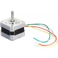
Library for A4988 stepper motor driver using timer interrupt

Update 4, October, 2023: I have made a new library for controlling stepper motor drivers that supports multiple motors and has a better acceleration algorithm. It can also coordinate xyz steppers.

This library is designed for AVR ATmega328 microcontroller, but with few adjustments can work with any AVR microcontroller with at least 3-4 Kb of flash program memory.
At the moment only one motor is supported.

Features

  • the interrupt can be triggered by Timer0 or Timer1
  • automatic microstepping mode selection
  • can work with constant and very low speeds
  • accelerated speed mode, with separate acceleration and deceleration settings
  • can work with only one pin of the microcontroller if the rest are hardwired

Nema 17 Bipolar Stepper Motor

Characteristics:


Features
Program Memory
Data Memory (SRAM)
All enabled
3552 bytes
40 bytes
Acceleration, no microstepping
3088 bytes
40 bytes
Microstepping, no acceleration
2104 bytes
14 bytes
No microstepping, no acceleration
1724 bytes
12 bytes

Compiled using avr-gcc (WinAVR 20100110) 4.3.3 and -Os optimization level and MATH_LIB = -lm.
If MATH_LIB = -lm is commented out in Make file, the memory with all functions enabled is 6520 bytes program and 304 bytes data memory.So allways uncomment MATH_LIB = -lm.


Saturday, June 3, 2017

Library for interfacing AVR microcontrollers with ET16312N VFD (Vacuum Fluorescent Display) driver

I had a broken Philips DVP5960 DVD player and I thought it's a good idea to salvage and use the VFD display in some project. And so this code was born.


Vacuum Fluorescent Display (VFD) from a DVD Player controlled by AVR MCU

To know more about the communication protocol between the microcontroller and the VFD driver chip, visit this post Salvage a VFD from a broken DVD.

Sunday, February 19, 2017

Library for reading internal temperature sensor on AVR microcontrollers

A few AVR microcontrollers have internal on-chip temperature sensors. The sensor is a diode that produces a temperature dependent voltage. This voltage is measured with the ADC. According to Atmel the typical accuracy of temperature measurements over the full temperature range of the AVR is ±10°C but after calibration the accuracy can be ±1°C over 20°C to 55°C using one-point calibration.


Library for reading internal temperature sensor on AVR microcontrollers

The calibration can be done using one-point calibration and compensation or two-point calibration and compensation. One-point calibration is the easiest - subtract the ambient

Friday, February 10, 2017

DHT11 Library Temperature and Humidity Sensor

 Interfacing DHT11 sensor with an AVR Microcontroller


This post describes how to interface a DHT11 temperature and humidity sensor with an AVR microcontroller and how to read and display the data on an LCD using the DHT11 library.

DTH11 is a low cost hobby digital sensor used to measure temperature and relative humidity. Digital means that the sensor incorporates a 8 bit microcontroller inside that takes care of ADC measurements for you. With an analog sensor you would have to set up an ADC and measure the sensor resistance directly and interpret the data. The DHT11 sensor uses a proprietary 1-wire protocol which is described down bellow.
The DHT11 sensor comes in a single row 4-pin package, breadboard friendly, and operates from 3.5 to 5.5V. It can measure temperature from 0-50 °C with an accuracy of ±2°C and relative humidity ranging from 20-95% with an accuracy of  ±5%. During measurement it draws 0.3mA and in standby 60uA.
The sampling rate is 0.5 Hz in some datasheets and 1 Hz on others; this means it is not recommended to read the sensor more than once every second or every two seconds. The recommended sample rate is 5 seconds to prevent the display changing to often.

DHT11 pinout

DHT11 Pinout

Sunday, January 1, 2017

Programming low frequency microcontrollers in WinAVR

Fixing clock incompatibility between microcontroller and ISP programmer

I was working on a low power project using ATtiny13 so I have decided to use the 128kHz internal oscillator as a CPU clock to save power. All went well but when I tried to modify the code and upload again an error message appeared in WinAVR saying

avrdude: initialization failed, rc=-1

After some research I found out what was going on.

Clock too slow for ISP programmer

The ISP programmer must have a speed lower than the microcontroller. 4 times lower is recommended.
The solution is to lower the ISP clock speed by using -B bitclock option. -B250 worked fine.

Example in avrdude. I use USBTinyISP programmer:

avrdude -p attiny13 -P usb -c usbtiny -B250

Append arguments in WinAVR

Open the make file and fin these lines (starting from line ~ 300)

AVRDUDE_FLAGS = -p $(MCU) -P $(AVRDUDE_PORT) -c $(AVRDUDE_PROGRAMMER)
AVRDUDE_FLAGS += $(AVRDUDE_NO_VERIFY)
AVRDUDE_FLAGS += $(AVRDUDE_VERBOSE)
AVRDUDE_FLAGS += $(AVRDUDE_ERASE_COUNTER)

Then append the line

AVRDUDE_FLAGS += -B250

Wednesday, August 24, 2016

Library for interfacing alphanumeric LCD modules with AVR microcontrollers

This library provides an interface between the microcontroller and LCD module. Note that this code is not for I2C modules.

Library for interfacing alphanumeric LCD modules with AVR microcontrollers - ATmega328P

Main features:

- Supports 16x1, 16x2, 16x4, 20x4, 20x2, 32x2, 40x2 LCD display modules
- Option for automatically wrapping the text to a new line
- Numbers can be padded with zeros to maintain user interface layout
- Scrolling a string of characters
- Includes two types of big digits numerical fonts for making a clock
- Has support for user defined fonts and other special fonts included by default in the LCD memory
- Support for 8 and 4 bit mode interface
- LCD backlight dimming or on/off control using PWM 

Contents:


Hardware interfacing ATmega328 AVR microcontroller with a 16x2 LCD module with PWM brightness control

This LCD modules can be connected in 4 bit mode or 8 bit mode. Using 4 bit mode is recommended because it uses less pins but the code is a bit more complex. In the following example I use 4 bit mode.


Hardware interfacing AVR ATmega328 with an 16x2 LCD module with PWM brightness control