After buying some ATtiny402 microcontrollers I've noticed that newer AVR
models from Microchip are now using the UPDI interface for programming.
Previously the programming was done using SPI or UART if a bootloader was
present.
Contents
What is UPDI and how do I use it?
UPDI stands for Unified Program and Debug Interface and is
proprietary to Microchip. In many ways is similar to 1 wire UART. The
main advantage is that it can be used for programming and also for debugging.
Now there is no need for SPI, bootloader, debugWire... It's all Unified in one
pin and one interface.
On certain devices such as ATtiny, the UPDI and Reset are on the same pin. In
each case, the UPDI pin can also be used as a GPIO pin. When UPDI and Reset
share the same pin, the functionality can be selected using the specific fuse.
By default the fuse is set to select UPDI as a pin function. If you change the
fuse and enable the Reset then you will need a 12V programmer to be able to
program the microcontroller.
To prevent false triggering when the line is idle, it is recommended to have a
pull-up resistor of at least 10k on the UPDI pin. Although some say that it
works without problems even without a pull-up resistor so if you are using the
UPDI pin also as a GPIO pin, you might consider not placing the resistor.
Source:
https://microchip.my.site.com/s/article/AVR---Hardware-Design-Considerations-for-UPDI-pin.
Can i manually reset the microcontroller when UPDI is shared with RESET?
When UPDI and RESET share the same pin, the external RESET function is
disabled so you can not place a button to manually reset the microcontroller.
It is possible to enable the RESET by changing the appropriate fuse, but then
you would need a 12V programmer to program the micro. But is a manual reset
that important? An alternative would be to cycle the power to the
microcontroller that would also cause a power on reset.
Tip: newer AVR devices can trigger a reset from software.
What hardware do i need for programming using UPDI interface?
There are many official programmers from Microchip for AVR devices such as the
well known
Atmel ICE. However a simple serial USB to UART converter can also be used. The benefit
of using a programmer such as Atmel ICE is that it can also be used for
debugging together with Microchip Studio where you can even use it as a logic
analyzer.
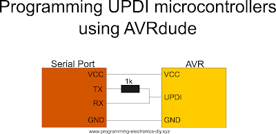
How to use a regular FTDI module with UPDI
Simply connect RX to UPDI pin and TX to UPDI pin but this time through a 1k
resistor.
What software do I need?
At the moment there are two options that I know of and tried: pymcuprog and
avrdude.
pymcuprog
is a command line Python utility and I believe is made by microchip.
avrdude
is another popular option and is my favorite since from my experience is
faster than pymcuprog and also doesn't require python to be installed.
Programming an UPDI device using avrdude, Microchip Studio and a USB to serial
module
UPDI programming can be done in a command terminal by invoking avrdude with
the proper arguments. In Microchip Studio the compiled file can be uploaded to
the microcontroller by using avrdude with a click of a button. To do that you
need to add an external tool as a programmer. If you need to know how to do
that, i have
a tutorial here.
The command is similar to how you would add a usbtiny programmer with a few
small changes.
-c serialupdi -p t402 -P COM3 -b 115200 -U flash:w:$(ProjectDir)Debug\$(TargetName).hex:i
-
-c: here programming interface is set to serialupdi
-
-p: this argument specifies the programmed device. In my case is
ATtiny402 which is defined as t402. To see a full list of microcontrollers
use avrdude -p ?
-
-P: serial port number. In my case is COM3.
-
-b: baud rate. Usually 115200. UPDI will detect and respond with the
same baud rate.
- -U: perform a memory operation.
-
flash: the memory type is flash. Other values can be eeprom, lfuse,
hfuse...
-
w: this field specifies what operation to perform and in this case is
write. In could be 'r' for read only.
-
$(ProjectDir)Debug\$(TargetName).hex: file name. The variables that
compose the filename are specific to Microchip Studio 7 and not avrdude.
-
i: file format field. Usually Intel Hex (i).
More
avrdude arguments.
Bonus tips
-
During programming, FLASH and EEPROM memories will be erased. To preserve
EEPROM memory during re-flashing, set the appropriate fuse bit.
-
To generate code for your AVR microcontroller using interactive GUI use
start.atmel.com.
-
Although by default the UPDI pin cannot be used as a GPIO, it can be used as
an input pin, to connect a button for example because it has an internal
pull-up resistor active when UPDI functionality is enabled. All you have to
do is place a button and check the pin state. When pin is low, the button is
pressed.
-
When having more than one project in one solution (more than one
microcontroller type), select the main.c file before uploading the code to
ensure the proper hex file will be used.
Configuring pins on UPDI microcontrollers
With newer AVR devices, configuring the pins as inputs, outputs, high or low, can be a bit confusing because there are more ways to do it. If you need to learn more about this, here are some useful resources:


