This is part 2 of the tutorial on SD card specifications. In part 1 of the tutorial we made functions necessary for SPI communication and card initialization in SPI mode. At the end of this second part you should be able to read and write an SD card.
Contents
5. Reading/Writing Data Blocks
5.2 CMD17 – Reading a Single Block
5.3 CMD24 – Writing a Single Block
5. Reading/Writing Data Blocks
5.1 Block Length
Block length can be set in Standard Capacity SD cards using CMD16 (SET_BLOCKLEN) however for SDHC and SDXC cards, the block length is always set to 512 bytes. Since nowadays most if not all cards are of high capacity type, we will only consider the latter in this tutorial.
5.2 CMD17 – Reading a Single Block
The command for reading a single block is CMD17 – READ_SINGLE_BLOCK with the format shown below.
SDHC and SDXC are block addressed and since a block has a set size of 512 bytes, an address of 0 (block 0) will read back bytes 0-511, address 1 will read back 512-1023 and so on. On the other hand, the Standard Capacity SD cards are byte addressed.
The flow of a single block read is shown in the diagram below:
After sending CMD17 the card will respond with R1 followed by a data block suffixed with a CRC. To know when the data is actually starting a start token is send by the card right before the single data block. The start token is 0b11111110 (0xFE) as depicted in the next image.
A function for reading a single block can be implemented like this:
uint8_t SD_Buffer[512 + 1]; // reserve 1 byte for the null
uint8_t SD_ResponseToken;

// CMD17 – READ_SINGLE_BLOCK
// For a 16MHz oscillator and SPI clock set to divide by 2.
// Thus, to get the number of bytes we need to send over SPI to reach 100ms, we do
// (0.1s * 16000000 MHz) / (2 * 8 bytes) = 100000
#define CMD17                   17
#define CMD17_CRC               0x00
#define SD_MAX_READ_ATTEMPTS    (0.1 * F_CPU) / (2 * 8)

/*______________________________________________________________________________________________
	Read a single block of data

	addr	32-bit address

	buff	a buffer of at least 512 bytes to store the data in

	token	0xFE – Successful read
		0×0X – Data error (Note that some cards don't return
			an error token instead timeout will occur)
		0xFF – Timeout
_______________________________________________________________________________________________*/
uint8_t sd_read_single_block(uint32_t addr, uint8_t *buf){
	uint8_t res1, read = 0;
	uint32_t readAttempts;

	if(SD_CardType == SD_V1_SDSC) addr *= 512;

	// set token to none
	SD_ResponseToken = 0xFF;

	sd_assert_cs();
	sd_command(CMD17, addr, CMD17_CRC);

	// read R1
	res1 = sd_read_response1();

	// if response received from card
	if(res1 != 0xFF){
		// wait for a response token
		// the host should use 100ms timeout (minimum) for single and multiple read operations
		readAttempts = 0;

		while(++readAttempts != SD_MAX_READ_ATTEMPTS){
			if((read = SPI_ReceiveByte()) != 0xFF) break;
		}

		// if response token is 0xFE
		if(read == 0xFE){
			// read 512 byte block
			for(uint16_t i = 0; i < SD_BUFFER_SIZE; i++) *buf++ = SPI_ReceiveByte();

			// add null to the end
			*buf = 0;

			// read and discard 16-bit CRC
			SPI_ReceiveByte();
			SPI_ReceiveByte();
		}

		// set token to card response
		SD_ResponseToken = read;
	}

	sd_deassert_cs();
	return res1;
}
The function needs two arguments: a 32-bit data address and a pointer to a buffer of at least 512 bytes to store the received data. Here the buffer is called SD_Buffer. The response token will be stored in the 1-byte global variable called SD_ResponseToken. When no error occurred the response token will be 0xFE otherwise it will hold the token error discussed in the next section.
After sending the read command, the response R1 is checked if is not 0xFF meaning the card responded and then we poll the card until we receive a token or timeout occurs.
According to physical spec at section 4.6.2.1:
The host should use 100ms timeout (minimum) for single and multiple read operations
To implement this timeout we can’t simply use a blocking function such as delay_ms() and a timer would be too expensive. Instead we could count the number of bytes sent over SPI and the number depends on the frequency at which the microcontroller operates and the SPI speed. The formula is already implemented in the given code above. For a 16MHz oscillator and SPI clock set to divide by 2 to get the number of bytes to send over SPI to reach 100ms, we do:
(0.1s * 16000000 MHz) / (2 * 8 bytes) = 100000
If the response token equals 0xFE then the 512 bytes data block is put into the main buffer. The 2 bytes CRC must be read even if not used.
5.2.1 Read Errors
If an error occurs when the card tries to retrieve the requested data, it will send a data error token instead of a data start token. This flow is shown in the diagram below.
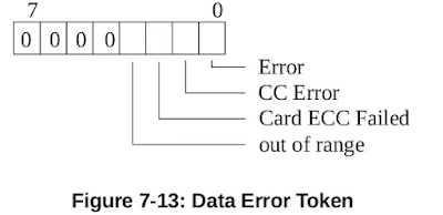
The format for the data error token is shown below.
Error: A general or an unknown error occurred during the operation.
CC Error: Internal card controller error.
Card ECC Failed: Card internal ECC (error correction) was applied but failed to correct the data.
Out of Range: data address argument is out of range.
The following defines can be used to check the error bits:
// Data Error Token
#define SD_TOKEN_OOR(X)		X & 0b00001000	// Data Out Of Range
#define SD_TOKEN_CECC(X)	X & 0b00000100	// Card ECC Failed
#define SD_TOKEN_CC(X)		X & 0b00000010	// CC Error
#define SD_TOKEN_ERROR(X)	X & 0b00000001
If the read function return a response R1 with an error, the data error token can be checked for more details on the cause of error(s). Not every card will return an error token instead they will timeout. If no error occurs R1 will be 0.
5.3 CMD24 – Writing a Single Block
The command for writing a single block is CMD24 – WRITE_BLOCK.
The flow for a single block write is shown below.
First send the write block command, wait for a response (R1), then send a start block token (0xFE) followed by 512 bytes of data to be written. After this we will wait for new type of token from the card: a data response token.
If the card accepts the data the response token will be 0bxxx00101. The card will then send busy tokens (0×00) until it has finished writing the data.
Here is the function for writing a single block:
// CMD24 – WRITE_BLOCK
// For a 16MHz oscillator and SPI clock set to divide by 2.
// Thus, to get the number of bytes we need to send over SPI to reach 250ms, we do
// (0.25s * 16000000 MHz) / (2 * 8 bytes) = 250000
#define CMD24                   24
#define CMD24_CRC               0×00
#define SD_MAX_WRITE_ATTEMPTS   (0.25 * F_CPU) / (2 * 8)
/*______________________________________________________________________________________________
	Write a single block of data

	addr	32-bit address

	buff	512 bytes of data to write from

	token	0×00 – busy timeout
		0×05 – data accepted
		0xFF – response timeout
_______________________________________________________________________________________________*/
uint8_t sd_write_single_block(uint32_t addr, uint8_t *buf){
	uint8_t res1;
	uint32_t readAttempts;

	if(SD_CardType == SD_V1_SDSC) addr *= 512;

	// set token to none
	SD_ResponseToken = 0xFF;

	sd_assert_cs();
	sd_command(CMD24, addr, CMD24_CRC);

	// read response
	res1 = sd_read_response1();

	// if no error
	if(res1 == 0){
		// send start token
		SPI_SendByte(0xFE);

		// write buffer to card
		for(uint16_t i = 0; i < SD_BUFFER_SIZE; i++) SPI_SendByte(buf[i]);

		// wait for a response (timeout = 250ms)
		// maximum timeout is defined as 250 ms for all write operations
		readAttempts = 0;
		while(++readAttempts < SD_MAX_WRITE_ATTEMPTS){
			if((res1 = SPI_ReceiveByte()) != 0xFF) break;
		}

		// if data accepted
		if((res1 & 0x1F) == 0x05){
			// set token to data accepted
			SD_ResponseToken = 0x05;

			// wait for write to finish (timeout = 250ms)
			readAttempts = 0;
			while(SPI_ReceiveByte() == 0x00){
				if(++readAttempts > SD_MAX_WRITE_ATTEMPTS){
					SD_ResponseToken = 0x00;
					break;
				}
			}
		}
	}

	sd_deassert_cs();
	return res1;
}
If after sending the write command 24 the response R1 is not an error we send the start token and then start transmitting the data in the buffer and then wait for the card to send a data response token.
Data accepted tokens are 0bxxx00101 (where x is a don't care), so we mask the upper three bits and see if it equals 0b00000101 (0×05). Finally we wait for the card to finish writing the data. The timeout is calculated like we did in the write function except this time the recommended timeout is 250ms instead of 100ms.
According to physical spec at section 4.6.2.2:
Maximum length of busy is defined as 250 ms for all write operations
There are 4 cases with this function that we should check after calling it:
-
R1 != 0×00 → Error writing block (parse R1 for details)
-
R1 == 0×00 and token == 0×05 → Success
-
R1 == 0×00 and token == 0×00 → Busy Signal timeout
R1 == 0×00 and token == 0×FF → No response after R1
At this point we now have all the necessary functions to initiate the SD card in SPI mode and read/write single data blocks.
6. Conclusion or Confusion
If you don’t understand it completely that’s normal; sometimes it takes reading different resources to clear things out.
In this tutorial I have covered the main aspects of the SD card specifications but if you want to know what other functionality they have, such as CRC and card encryption, take a look at the SD specifications manual linked below. I also recommend reading the one from SanDisk Secure Digital that I personally found easier to follow. I have included the PDFs as a download link because they initially didn’t have bookmarks so I added most of them to be able to navigate easier using a PDF reader.
Let us know if this was useful, or if you have any questions leave them in the comment section below.
You can also download this tutorial in a PDF format at the link below. If you find it useful, consider a small donation at the link provided.
SD card tutorial - Interfacing an SD card with a microcontroller over SPI, v1.0, 2022.pdf
7. Links
-
SD Specifications, Physical Layer, Simplified Specification v2.0, 2006.pdf – added bookmarks
-
Memory Card - SD - SanDisk Secure Digital Card v1.9, 2003.pdf – added bookmarks
-
SD cards on Wikipedia – https://en.wikipedia.org/wiki/SD_card


could you also provide sample code you used to write data into the SD card?
ReplyDeleteSure. Here is an example on how to use the "sd_write_single_block" function to write data to sd card. This assumes that a block consists of 512 bytes. Although this is usually the case, some cards could have a block defined as 1024 bytes for example.
Delete// 512 bytes of data to be written on a single block
// could be populated in a for loop
uint8_t data[512];
// SD card block address
uint32_t block_address = 0;
// Write on block 0 (from byte 0 to byte 511 on the card)
sd_write_single_block(block_address, data);
// Increment address by one block
block_address++;
// Write on block 1 (from byte 512 to byte 1024 on the card)
sd_write_single_block(block_address, data);
But without a file system, the card is used like a huge EEPROM memory. To keep track on where the data is, you need a file system such as FAT16 or FAT32. If you need a library that integrates both an SD card driver and a file system you can find it here: https://www.programming-electronics-diy.xyz/2022/07/sd-memory-card-library-for-avr.html