In this article I will be explaining how a pyroelectric (PIR) sensor works and show the reverse engineered schematic simulated in LTspice. The schematic is for NV-1111.35 outdoor PIR sensor used to switch a mains light and has 3 potentiometers for setting SENSITIVITY, LUX and TIMEOUT.
This sensor is based on a popular three stage op-amp topology. Understanding this can help you understand other pyroelectric sensors as well and also something about active filters using LM324 and removing and setting a DC voltage bias.
How a PIR sensor work
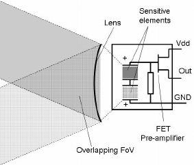
This particular sensor board is using the D203S PIR sensor. Pyroelectric passive infrared (PIR) sensors detect infrared (IR) radiation. A warm object emits infrared energy that is not visible with a human eye. Since the purpose of the sensor is to detect motion not only heat, there are two parts sensitive to IR that look like two little windows or slots.

|
|
The sensor window is actually split into two parts |
This two elements are used in series with opposite polarity so the average
radiation is cancelled out. When the sensor is idle both slots detect the
same amount of IR so the ambient temperature won't trigger the sensor. If a
warm body like a human or animal passes by the infrared energy it is first
detected by an element then by the second one and so generating an AC
signal. A mosfet is also included to buffer the weak signal produced by the
PIR sensor.

|
|
PIR sensor diagram |

|
|
Image from AN4368 - Signal conditioning for pyroelectric passive
infrared (PIR) sensors |
The signal produced by the PIR sensor is around 1mVpp and it has a DC offset voltage that can vary from 0.3V to 1.2V.
Fresnel lenses
In order for the sensor to cover a wide angle, Fresnel lenses are mounted in
front of it. They are cleverly designed with many areas of Fresnel lenses
arranged in a way so they can split the detection area into multiple sections.
This for the sensor looks like it has not only two detection elements but many
pairs of them. So even a small movement can trigger both elements.

|
|
Image from D203S datasheet |
PIR sensor circuit explanation and schematic using the LM324N op-amp
The board can be powered from 5V to 12V however the value of the components are designed for 8V to 12V. It can work on 5V but the voltage division created by R17 and R18 must be changed.
Power consumption is very low: 1.5-2mA.

|
|
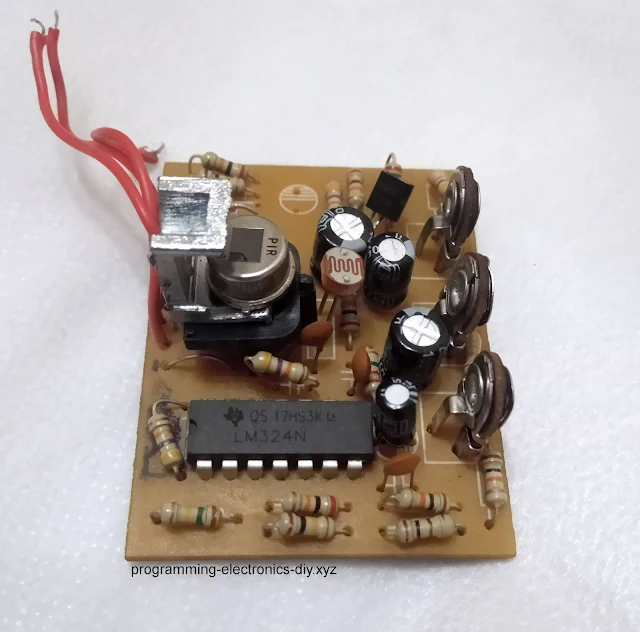
Parts of solder mask were burned due to the power board short-circuit
but only the op-amp was damaged on the main board |
 |
| Outdoor PIR sensor board schematic (click to enlarge) |
This op-amp architecture consists of three stages.
Stage 1
The first architectural stage amplifies the signal. It cancels the DC part of the signal and filters the high frequency noise that could lead to false detections.
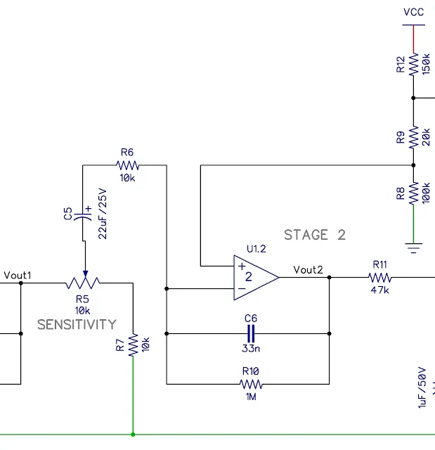
Stage 2 - Setting PIR sensor sensitivity
Stage 3 - Setting PIR sensor timeout and light threshold
In this last stage 3 the signal from stage 2 is again inverted and filtered by the R11 and C7 with a 3.38 Hz cut-off frequency but this time the last two op-amp are used mostly as comparators. The non-inverting input is set by R12, R9 and R8 at 44% of VCC, one diode voltage drop above the ratio in stage 2.

|
|
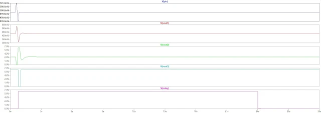
PIR sensor signal conditioning ploted in LTspice |
The schematic was simulated in LTspice. In the first plot there is Vpir that represents the 1mV signal from the sensor around 500mV offset voltage.

|
|
PIR sensor simulated in LTspice |
In the next tutorial I will be presenting the capacitive power supply.


Süper bir calişma ..sürekli yazinizi okuyorum. ve bu devreyi yapmak.
ReplyDeleteThank you. I'm glad it was useful.
DeleteSevgili arkadaşim.
ReplyDelete5v veya 12v için R17 ve R18 nasil ayarlanir. Ögrenmek istiyorum. Formul nedir.
nasil deneme yapilir.
Try and swap the values. Make R18 100k and R17 20k. At lower voltages the non-inverting pin of the op-amp will always be higher than the inverting pin, making the signal to the relay always high. Hope it helps.
DeleteI have linked at the end of the page the LTSpice simulation and the PCB in DipTrace if you need them.
DeleteTeşekkür ederim.ilginiz için
ReplyDeleteHi, thanks for your content.
ReplyDeleteI will to remove sensitivity pot for my schematic.
what is the equivalent circuit?
The pot can be replaced by a fixed resistor. You can find the redraw schematic at this link https://drive.google.com/file/d/1yL3QXjgciPmGxRemkGyJxisyB-IQ2p_x/view?usp=sharing
DeleteThe resistor can be any value between 0 and 10k. I would try a 2.2k or 4.7k. The higher the value the lower the sensitivity if I remember correctly.
I tried to get result but faild.
ReplyDeleteit blinks.
2 sec off and about 3 sec on.
Try with a 10k resistor maybe it's too sensitive and also check the connections. Connect the node where the pot wiper was to the junction between the new resistor and the pulldown resistor. I did fix one like that that had a broken pot and it works very well.
DeleteAlso check the timeout pot if the timeout is not too short
DeleteHi. Thanks for an excellent article. I have one of these pir circuits which is misbehaving. As soon as the last stage times out, the relay goes off for almost a second and then goes on. You can hear the relay ticking for a second. In effect, the relay almost always remains on. Appreciate your reply.
ReplyDeleteHi. Hope I can help but the potential problems could be many. My first step in troubleshooting a circuit is to first examine with a magnifying glass if for shorts, smoke or bad solder joints. If I remember correctly that was also my issue. The voltage on the (-) pin of the last op-amp #4 would not go higher than the voltage of the (+) pin so the output of the op-amp would be always high. I remember that I had to change the op-amp but I think because of other issues, then I lowered the value of resistor R17 in the voltage divider to get a lower voltage on the (+) pin so the (-) pin can go higher. I would also check the timing capacitor and potentiometer off circuit. Good luck.
DeleteYes. By removing the LDR the sensor should work at night and during the day as well.
ReplyDeleteHi, Thank you for an interesting functional explanation. I have a need to extend he timeout and keep the power relay on for a longer time. Could you please explain the easiest way to increase the timeout time to about the double from the present value.
ReplyDeleteIt's easy. Replace the timing potentiometer (R19 in stage 3) with a fixed resistor with a larger value. If the potentiometer is 2M use a 4M resistor or multiple is series if you don't have one that large.
Delete