Tuesday, November 9, 2021

Mains short circuit protection, current limiter using incandescent light bulb in series

This is a short circuit protection unit that will limit the current when working with mains voltage in case of a short circuit. It is useful for testing repaired equipment and can also be used to test transformers and light bulbs as a bonus. If a short circuit would to occur all that will happen would be to light up the incandescent light bulb thus protecting the equipment and household wiring.

Mains short circuit protection and current limiter using tungsten lamps in series

How to build a mains short circuit protection unit for testing and repairing electrical equipment and transformers

The working principle of this unit is very simple - an incandescent tungsten light bulb is placed in series with the load. If the current draw by the load is small comparative to the bulb's power, the light bulb will not glow and it's resistance will be low. In case of a short circuit the higher current draw will cause the light bulb to heat up and glow and that will increase the resistance of the tungsten filament therefore limiting the current.

When cold the incandescent tungsten filament has a low resistance (~25-50 ohms for a 75W bulb). When mains power is applied to it the filament will get glowing hot and the hotter a metal is the more agitated the electrons are, bouncing everywhere, and so creating the effect of a higher resistance when hot versus when cold.

Friday, October 22, 2021

DAC library for MCP4706, MCP4716, MCP4726 and AVR microcontrollers

This library is intended for the MCP47x6 series of DAC devices that includes MCP4706 (8-bit DAC), MCP4716 (10-bit DAC) and MCP4726 (12-bit DAC).

DAC library for MCP4706, MCP4716, MCP4726 and AVR microcontrollers

Table of Contents


MCP47x6 DAC pinout

MCP47x6 DAC pinout

1 - VOUT: this is the DAC analog output voltage. In Normal mode, the DC impedance of the output pin is about 1Ω. In Power-Down mode, the output pin is internally connected to a known pull-down resistor of 1 kΩ, 125 kΩ, or 640 kΩ. The VOUT pin can drive up to 100 pF of capacitive load in parallel with a 5 kΩ resistive load. It is recommended to use a load with RL greater than 5 kΩ. Driving large capacitive loads can cause stability problems for voltage feedback op amps.

Tuesday, October 19, 2021

I2C and TWI (Two Wire Interface) library for AVR microcontrollers

In the last article I talked about How I2C and TWI protocol works and we saw that they are mostly the same so this library works for both I2C and TWI serial interfaces. You don't have to know every detail about how the I2C protocol works but I strongly recommend reading the article to have a general idea about it, and that way it will be easier to use this library.


Using the I2C, TWI library with an AVR microcontroller

Setting the library file

As always, first include the library file:

#include "twi.h"

Most AVR microcontrollers have two TWI modules TWI0 and TWI1 so to choose between the two there is the following line of code:

#define TWI_MODULE_NUMBER	0 // TWI module 0 or 1

The default module is TWI0.

Functions


void TWI_Init(uint32_t frequency)

Used to initialize the TWI module. This will set the TWI bit rate and enable global  interrupts. 400kHz is the maximum TWI speed that regular AVR microcontrollers supports although I have managed to talk to a DAC at 577kHz.

frequency:  can be one of the following constants or any value between 100-400kHz.

#define TWI_400KHZ	400000 // Hz
#define TWI_100KHZ	100000 // Hz

Saturday, October 16, 2021

How the I2C and TWI (Two Wire Interface) protocol works

I2C is a two-wire serial bus communication protocol invented by Phillips in 1982. TWI stands for Two Wire Interface and, for the most part, this bus is identical to I²C. The name TWI was introduced by Atmel and other companies to avoid conflicts with trademark issues related to I²C. Because these two protocols are almost the same I will refer to them interchangeably throughout the course of this article.

This protocol is very used nowadays by all sorts of devices such as DACs, LCDs, sensors, etc. so it's worth learning about it.

As a disclaimer I need to mention that most parts of this article contains fragments from the ATmega328, 324 datasheet and MCP4706 datasheet. I liked how they explained the I2C, TWI protocol  and since not many people read the datasheets I want to share this information with anyone interested in the TWI protocol.

If you're interested in a I2C, TWI library it can be found at this link I2C, TWI library.

Features

  • 7-bit Address Space Allows up to 128 Different Slave Addresses
  • Multi-master Arbitration Support
  • General call addressing

The I2C interface specifies different communication bit rates. These are referred to as Standard, Fast or HighSpeed modes.

  • Standard mode: bit rates up to 100 kbit/s
  • Fast mode: bit rates up to 400 kbit/s
  • High-Speed mode (HS mode): bit rates up to 3.4 Mbit/s

High-Speed mode is currently unsupported by the TWI.

Table of Contents


Two-Wire Serial Interface Bus

The TWI protocol is able to interconnect up to 128 different devices using only two bidirectional bus lines: one for clock (SCL) and one for data (SDA). The only external hardware needed to implement the bus is a single pull-up resistor for each of the TWI bus lines. All devices connected to the bus have individual addresses, and mechanisms for resolving bus contention are inherent in the TWI protocol.

TWI Bus Interconnection

The number of devices that can be connected to the bus is only limited by the bus capacitance limit of 400pF and the 7-bit slave address space. The SCL and SDA pins are open-drain configurations. For this reason these pins require a pull-up resistor.

Saturday, May 29, 2021

Bluetooth Stereo Audio Receiver JDY-62 module and the Bluetooth 4.0 CSR dongle transmitter

There are many solutions for streaming audio from your computer to Bluetooth devices. One affordable Bluetooth transmitter/receiver pair is presented here. With these two Bluetooth modules, streaming audio from PC is very easy.

JDY-62 is an affordable Bluetooth stereo audio receiver module with great sound qualities for the price provided the ground connection is properly made (more on this later). To send audio from PC to the JDY-62 module I have used the Bluetooth 4.0 CSR dongle transmitter that works well on Windows 10 and acts like a sound card that you can select in the media player.

Bluetooth Stereo Audio Receiver JDY-62 module and the Bluetooth 4.0 CSR dongle transmitter

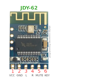
JDY-62 module pinout

JDY-62 module pinout

Monday, May 10, 2021

Pinning files on LibreOffice taskbar and other apps in Windows 10 - an alternative to recent files

I was searching a way to show the recent files in LibreOffice by right clicking on the pinned app on the taskbar but it appears it can't be done in Windows 10. But, there is a better way - pinning the most used documents.

Pinning files on LibreOffice taskbar in Windows 10

To pin your favorite files on LibreOffice (or any other apps like folders in Explorer) first pin the application on the Windows taskbar by dragging the icon from the desktop to the taskbar.

Pinning files on LibreOffice taskbar in Windows 10 - 1
Click to enlarge

Then to pin a file, drag the file from Windows explorer to the desired app on the taskbar.

Pinning files on LibreOffice taskbar in Windows 10 - 2


From now on you can just right click on the taskbar app and select which file do you want to open.

Wednesday, April 21, 2021

Building a Digital Clock with RGB Lamp & Spherical Shelf DIY

Here is how to build a simple digital wall clock encased in a spherical shelf that could make a nice gift for someone.

The clock is based on an ATmega328PB microcontroller that is using a 32.768 kHz crystal for time keeping. It also has 6 RGB leds that act as a night lamp or simply for aesthetic purposes.

Digital Clock With RGB Lamp & Spherical Shelf DIY

Thursday, February 25, 2021

Playing music and tones using a piezo buzzer - library for AVR microcontrollers using timer interrupt | ATmega328

This is a library for playing monophonic music using PWM and a piezoelectric buzzer. Monophonic means it can play only one note at a time. Regardless, it can produce some nice music. Optionally a led can be made to blink with the music rhythm.

Apart from playing songs it can also be used for tone generation useful in projects where audio indicators are needed.

All you need is a 16-bit timer that can be one of the following: timer1, timer3 and timer4 (provided that the microcontroller has them) and an 1ms interval interrupt where to place the main function. This is needed because the notes must have a certain duration.

Playing music and tones using a piezo buzzer - library for AVR microcontrollers using timer interrupt | ATmega328P, ATmega88

Playing music on a piezoelectric buzzer using PWM and a microcontroller


Saturday, February 6, 2021

Colorspace conversion between RGB and HSL library code for AVR microcontrollers | ATmega328P

I had a project where I needed to crossfade RGB colors and I thought why not using the HSL color space instead of the RGB color space because with the HSL the code looks neater and the Hue (color), Saturation and Lightness can easily be modified to create all kinds of light effects.

Colorspace conversion between RGB and HSL library code for AVR microcontrollers | ATmega328P

Converting HSL to RGB

HSLtoRGB(hue, saturation, lightness, rgb[])

Thursday, February 4, 2021

How to control RGB leds | RGB fader library for AVR ATmega328P

RGB leds are fun and because they can be used in many projects I have decided to make a library to easily crossfade the colors of one or multiple RGB leds.

To see this library used in a real project, check out this video Digital Clock With RGB Night Lamp & Spherical Shelf.

How to control RGB leds | Crossfading RGB leds | Library for AVR ATmega328P

Crossfading an RGB led in the RGB colorspace

With 8 bits we have 256 values from 0 to 255 that represents the duty cycle - how long a led will be on then off in a period. For example setting the RED led to 255 and GREEN and BLUE to 0 will result in RED color. Or RED 255, GREEN 0 and BLUE 255 will show a purple color. All leds on (255 value) will result in a white lite. So this is how a certain color can be produced but how to cycle through all the possible combinations?

Crossfading an RGB led in the RGB colorspace 1

First the red color is set at 255 and green and blue to 0. Then the red will be decremented and the green will be incremented. When the red will be 0 and green 255 we change the fading up and fading down colors.

Wednesday, February 3, 2021

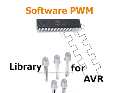
Multi-channel software PWM library for AVR microcontrollers | ATmega328P

What you do when you run out of PWM pins on hardware? You make software PWM of course. This library is based on "AVR136: Low-Jitter Multi-Channel Software PWM" application note. It supports up to 10 PWM channels (more can be added) and it's suitable for led dimming, DC motor control and RGB led controller.

Multi-channel software PWM library for AVR microcontrollers | ATmega328P

Since this method is already explained in the AVR136 app note I won't go in to too many details. So the basic principles behind software PWM are this. A timer interrupt is set to trigger every 256 system clocks. For 8 bit timers the interrupt is on overflow and for 16 bit timers is on compare match. A 16 bit timer has the advantage that the base frequency can be modified. On every interrupt a variable "softcount" is incremented from 0 to 255 and each time is compared against each PWM channel. At the beginning of the cycle the pins are set high and when "softcount" equals to a channel's set value then the specific pin is set low. On 8MHz CPU the ISR takes between 4 and 10us to execute the code depending on how many channels and on how many ports there are. The size of the "softcount" variable dictates the PWM resolution and it is set to 8 bits. 

Saturday, January 23, 2021

Binary Code Modulation (BCM) aka Bit Angle Modulation (BAM) library for fading leds for AVR microcontrollers

Binary Code Modulation (BCM) was invented by Artistic Licence and is a form of PWM but not really. The main advantage over software PWM is the low CPU usage regardless of how many channels it controls.

This library provides a fast implementation of Binary Code Modulation useful for controlling RGB leds and dimming multiple leds for creating animations like led cubes and includes an array for logarithmic brightness. A complete cycle takes 8 timer interrupts and each interrupt takes only 4us on a 8MHz CPU. The leds can be on different ports.

Bit Code Modulation (BCM) aka Bit Angle Modulation (BAM) library for RGB led dimming - 8-bit

How Binary Code Modulation (BCM) works and how it differs from PWM

To dim a led with PMW is simple. If you want the led to be half as bright you turn the led on for 50% of the cycle and 50% for the other half. Or 20% on and 80% off for an even dimmer led.


PWM example

Bit Angle Modulation uses the weight of each bit in a binary number. For example in one byte there are 8 bits with numbers from 0 to 7. Bit 0 is called the Least Significant Bit (LSB) and it's weight is 1. Next bit 1 has a weight of 2, bit 2 has a weight of 4, then 8, 16, 32, 64 and 128. Bit 7 is called the Most Significant Bit (MSB) because it has the highest weight - 128.

8-bit binary weight

Monday, January 18, 2021

7 segment display library for AVR microcontrollers | ATmega328P

There are many ways to control a seven segment display - using a dedicated IC or shift registers which are preferred because they don't require many pins. However this library is made for when you have the segments driven directly from microcontroller pins and each digit is controlled using a transistor.

You have the option of padding the numbers with zeros and displaying them at a certain position, useful for making digital clocks.

To see this library used in a real project, check out this video Digital Clock With RGB Night Lamp & Spherical Shelf.

Seven segment display library for AVR microcontrollers

What is a 7-segment display

As the name suggests it is a display that is made up of 7 segments. Each segment is simply an LED. Including the dot there are actually 8 LEDs and this fits perfectly on an 8-bit microcontroller's port. This display is mainly made for numerical values but some alphabetical characters can be displayed as well.

Types of 7 segment displays

There are two types of seven segment displays - common cathode and common anode. Common cathode displays have all the ground sides (cathodes) of the LEDs connected together while common anode displays have all the positive sides (anodes) of LEDs tied together.

The 7 segment display can have from 1 up to 6 or 8 digits. One digit can display numbers from 0 to 9 and a dot for numbers with decimals. On 4 digit seven segment display the maximum number that can be displayed is 9999.

7 segment display internal equivalent circuit OPD-Q5621LE-BW
Figure 1: Internal equivalent circuit of a 7 segment display from OPD-Q5621LE-BW datasheet


Saturday, January 16, 2021

Read and debounce multiple buttons using interrupt on AVR microcontrollers

This library provides an easy way for reading and debouncing one or multiple buttons connected to a microcontroller. Apart from basic functionality, the library provides some extra functions such as reading a combination of buttons, and detecting a button long press or a double pressed button. These are especially useful in a low button count system.

There are many methods of reading buttons. The simplest way is having each button connected to a microcontroller pin, and the other button pin connected to ground. The microcontroller pin is set in output mode with the internal pull-up resistor activated. When the push button is pressed, the pin will be pulled to ground indicating that a button in pressed.

After a certain number of buttons, the above method becomes impractical since microcontrollers with high pin count are much more expensive. In that case multiplexing is used like on a keyboard, where the buttons are arranged in a grid having x number of pins for columns and y pins for rows.

This library uses the first method for when the buttons are connected directly to a microcontroller pin. Hopefully, when I'll get the time I will adapt the library to take inputs from a matrix.

Multiple buttons can also be read by a single ADC pin.


Button debouncing library for AVR microcontrollers

Contents


What is button debouncing

Saturday, January 9, 2021

millis and micros library for AVR microcontrollers - milliseconds and microseconds time tracking

Having precise timing in microcontrollers is important in many projects. For this you can use the two libraries presented in this article - millis & micros.

millis library triggers a timer interrupt every 1 millisecond and increments the milliseconds variable. The user can select the size of the milliseconds variable ranging from char (8 bits) to long long (64 bits) with an overflow from 255 milliseconds to 584.9 million years.

micros library is almost the same as millis but for microseconds. The overflow is between 255 microseconds and 584942 years.

For both libraries the user can select which timer to use: Timer0, Timer1, Timer2, Timer3 or Timer4.

In the case of millis library, it is recommended that other interrupts take less than 1 millisecond to complete otherwise the millis timer interrupt will be delayed. For the micros the ISRs must finish in less than 100 microseconds. The faster the CPU clock the better.

For the milliseconds and microseconds variable decide if you really need a 32 or 64 variable (long and long long) because the bigger the variable the longer it takes to increment it. For example on a 1MHz CPU it takes about 77 microseconds to increment a long long variable.

millis & micros library for AVR microcontrollers


Thursday, January 7, 2021

ISP programming rig for microcontrollers

I had to program many types of microcontrollers over the years and so I was thinking why not build a simple programming rig to make things easier. This rig is for the In-system programming (ISP) method and not for the UART method.

How to easily upload the code to any microcontrollers using ISP rig

The board in the above image is not the programming rig but a digital clock shown as an example. Notice the 6 pin header near the cap. The pins are not soldered through hole but on SMD pads. This way it can be easily de-soldered after finishing the project and on some space constrained projects this is a must.