Here is how to build a simple digital wall clock encased in a spherical shelf that could make a nice gift for someone.
The clock is based on an ATmega328PB microcontroller that is using a 32.768
kHz crystal for time keeping. It also has 6 RGB leds that act as a night lamp
or simply for aesthetic purposes.
Building a Spherical Shelf
The spherical shelf is made out using 2mm thick plexiglass. The plastic parts can be cut manually or using a local shop that can cut acrylic sheets. I have cut it manually using a soldering gun and I can say it involves lots of work sanding the edges afterwards.
If you want you can get a free copy of the shelf CAD project on Onshape at this link https://cad.onshape.com/documents/100e807972686d741f1187eb/w/eec98b6c3c3b7f00df273d8e/e/993404d90707c22714952e45. There you can also find the cutting templates if you plan on cutting it manually. These can be printed on 4 x A4 paper sheets with a 1:1 scale.

|
|
Cutting templates pinned on the plexiglass sheet using scotch tape |
After cutting the necessary parts can be interlocked in place without any glue. In the center should remain a square opening of 80 x 80 mm where the clock will be mounted.
In the back there is a piece of plastic with two holes in the form of a upside down keyhole shape where the two screws are.
The clock enclosure
The dimensions for the clock enclosure and template for drilling the holes can be found in this Inkscape file clock drawings.svg. The scale is 1:1.
The backside cover is held in place by some tape. Before the sides were glued I have applied some white sticker on the inside except for the slot in the middle that goes on all four sides so the light from the leds can pass through.
Dimensions for 2mm thick plexiglass sheet:
Front side: 80 x 80 mm
Top and bottom sides: 80 mm width, 55 mm depth
Left and right sides: 55 mm depth, 76 mm height
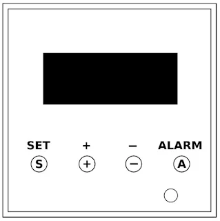
For the front cover I printed on a white paper this template and cut out the part where the display will be and the circle for the led alarm indicator then drilled 4 holes with a 5 mm drill for the buttons.
The buttons
The push buttons can't reach through the front panel because of the display thickness so I have used some pieces from plastic nails with the part that touches the push buttons melted so it doesn't come out the box. There are however longer buttons commercially available and those would be a better solution.
Improving the seven segment display contrast
I had some polarized films from a broken LCD TV and I've noticed that the contrast of the display was improved by placing it at 45 degrees in front of the display. Be sure to glue it before assembling the enclosure.
Mounting the PCB
To have something in which to screw the screws I made 4 squares from hard foam
sheets of 10 x 10 mm with the same height as the display so when mounted the
display will be exactly in contact with the front panel.
The power cord is held in place by some electrical tape. Much better strain relief methods can be found though. Perhaps a connection using two pin header connectors so the clock can be easily pulled out.
Schematic
The schematic can be downloaded from here (clock schematic.png) as a png image or as a project in DipTrace at the end of this page.
The clock can be powered from any 5V phone charger that can output minimum 300mA that is the total current consumption when the RGB leds are on. With the leds off the current draw is around 75mA.
At the power input there is a 5.6V zener diode that is used to protect the microcontroller from over-voltage and reverse voltage in case you mix the charger and plug in a 12V adapter (definitely it didn't happen to me and I didn't place the zener afterwards). If the charger has short circuit protection in the worst case the Zener will blow out but the rest of the circuit will be fine after replacing the diode.
All mosfets are NX7002AK smd N-channel mosfets that I bought from Farnell and
are very affordable. Even the cheapest mosfets will do since there is not much
current involved so the mosfet on resistance doesn't matter.
The 6 smd leds were desoldered from a 12V RGB led strip. Cheaper than to buy them separately. The 27 ohm resistors are 1206 smd resistors so they can dissipate the heat better. 0805 will work but they get a bit warm.
The microcontroller must be ATmega328PB and not ATmega328P. They are almost
the same with the exception of two pins that differ so they are not 100% pin
compatible. ATmega328PB is newer.

|
| Backside |
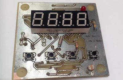
Disregard the photo transistor below the buttons. I thought it would be a good idea to dim the leds based on the light intensity but since it is not powered by batteries it doesn't really matter. I replace it with the led alarm indicator that was initially above the display.

|
|
Detail with the programming jig |
The schematic and PCB layout can be downloaded at the end of this article.
You will need DipTrace installed for this but it's free.
The code
This clock project is using the following libraries:
Binary Code Modulation (BCM)
for driving the RGB leds.
buttonDebouncer for reading the buttons.
display7seg to drive the 7 segment display.
RGBvsHSL for converting RGB values to HSL.
rgbFader to cross-fade RGB colors.
chipTunes to generate tones on the piezo buzzer.
All the library files are included in a zip file down below. You can use
either Atmel Studio or WinAVR to upload the code using the ISP method so you
don't need a bootloader. Haven't tried Arduino but I guess it's possible. To
open the project in Atmel Studio (now called Microchip Studio) use the
Digital Clock With Night Lamp.atsln file.
The fuses
If you have avrdude installed you can modify the microcontroller's fuses using a command prompt window and pasting this command line:
avrdude -c usbtiny -p atmega328pb -U lfuse:w:0xE2:m
usbtiny is the programmer so replace it with your programmer type. This command line will modify only the low fuse to disable the internal CPU clock division by 8. After this the internal CPU clock will be 8MHz instead of 1MHz.
Using a 32.768 kHz watch crystal with an AVR microcontroller
Many AVR microcontrollers such as ATmega328PB have hardware support for using a 32.768 kHz watch crystal provided that the device is using the internal RC oscillator. That means you can't use a 16MHz crystal and a 32.768 kHz crystal for example. That's because when you clock the device using an external crystal, the crystal must be connected to XTAL1 and XTAL2 and the watch crystal must be connected to TOSC1 and TOSC2 and both these peripherals are shared by pins PB6 and PB7 respectively.
When AS2 bit in ASSR register is set, PB[7:6] is used as TOSC[2:1] input for the Asynchronous Timer/Counter2. So every time the watch crystal is oscillating the Timer 2 counter will be incremented.
ASSR = 1 << AS2; // use the 32.768 crystal at TOSC1
Next the Clear Timer on Compare Match (CTC) mode is selected and prescaler is set to 1
TCCR2A = 1 << WGM21; // CTC mode
TCCR2B = 1 << CS20; // prescaler 1
We also need an interrupt triggered after the crystal will oscillate a certain number of times
TIMSK2 = 1 << OCIE2A; // enable Output Compare A Match interrupt
The crystal oscillates 32768 times per second and time 2 is an 8 bit timer meaning it can only count to 256 values (0 - 255) so we cannot trigger an interrupt every second.
(32768 / 1024) - 1 = 31 so the OCR2A is set to 31. After the crystal oscillates 31 times a timer interrupt will be triggered.
OCR2A = 31; // for 0.946 ms (32768 / 1024) - 1
(1 / 32768) * 31 = 0.946 milliseconds interrupt.
So why 32768 / 1024 ? First the result must be an integer not a float because OCR2A cannot have decimals. Instead of 1024 I could use 512 and the OCR2A would be 63 but that would give an interrupt every 1.92 ms and I needed an interrupt roughly every 1 ms for the buzzer, buttons and the display so 1024 fits nicely.
In the ISR(TIMER2_COMPA_vect) interrupt handler the variable timerISRCount is incremented on each interrupt and when it equals 1024 that means a second has passed. To blink the display colon every 500ms the variable is also checked for when it equals 512 (1024 / 2).
Usage
Setting the time
Press and hold the SET button for 2 seconds. The hours will start flashing. Press (+) or (-) to change the hours. Press SET again once or twice to set the minutes and seconds.
To exit from any setting mode press the ALARM button or wait 10 seconds without pressing any button.
Setting the alarm time
Press SET and ALARM at the same time then SET again. The hours will start flashing. Press SET to modify the minutes. The led alarm indicator should turn on indicating the alarm will trigger at the specified time. After triggering, the alarm will be turned off automatically after 1 minute and also the RGB lamp if it was on. The alarm can also be turned off by pressing any button.
Display the alarm time
Hold down the ALARM button.
Turning the alarm on/off
Double press the ALARM button until the led alarm indicator will toggle.
Seconds display
Hold down the (+) button.
Turning the RGB lamp on/off
Hold down the (-) button for 2 seconds until the lamp will toggle on or off. There are two RGB modes: n1 and n2. In mode n1 the lamp will cycle through the RGB colors. In mode n2 the light color can be changed by pressing and holding (+) or (-) buttons.
Changing the RGB mode
Press SET and (-) at the same time. The new RGB mode will be displayed. In mode n2 the light color can be changed by pressing and holding (+) or (-) buttons.
Changing the lamp brightness
Press (+) and (-) at the same time. The lamp brightness value should appear. Use (+) and (-) buttons to change the brightness.
Download
This zip file contains the schematic and PCB layout for DipTrace and the necessary code that can be compiled and uploaded to the microcontroller using Atmel Studio (Microchip Studio) or WinAVR or Arduino but haven't tried that.
Version 1.0


No comments:
Post a Comment