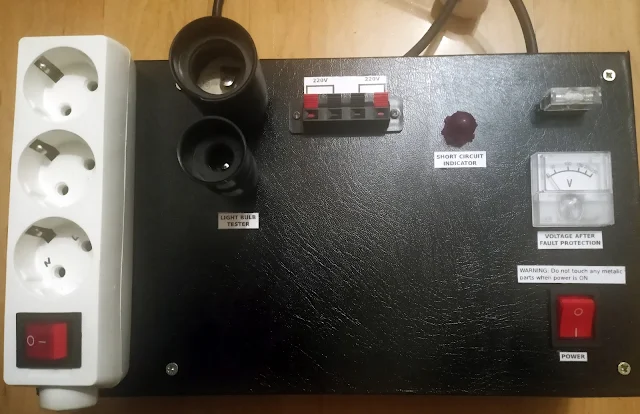
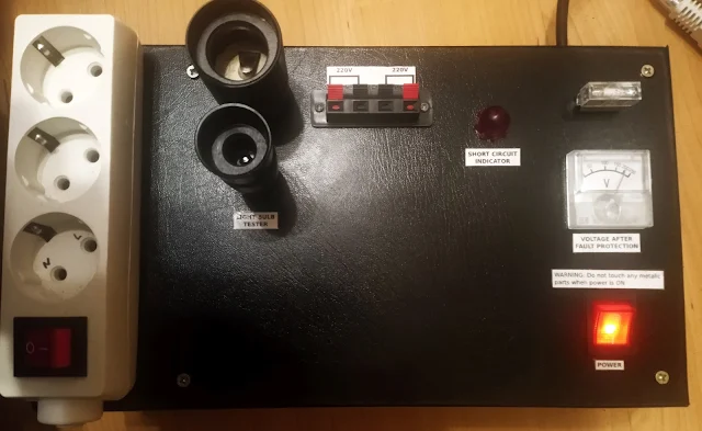
This is a short circuit protection unit that will limit the current when working with mains voltage in case of a short circuit. It is useful for testing repaired equipment and can also be used to test transformers and light bulbs as a bonus. If a short circuit would to occur all that will happen would be to light up the incandescent light bulb thus protecting the equipment and household wiring.
How to build a mains short circuit protection unit for testing and repairing electrical equipment and transformers
The working principle of this unit is very simple - an incandescent tungsten light bulb is placed in series with the load. If the current draw by the load is small comparative to the bulb's power, the light bulb will not glow and it's resistance will be low. In case of a short circuit the higher current draw will cause the light bulb to heat up and glow and that will increase the resistance of the tungsten filament therefore limiting the current.
When cold the incandescent tungsten filament has a low resistance (~25-50 ohms for a 75W bulb). When mains power is applied to it the filament will get glowing hot and the hotter a metal is the more agitated the electrons are, bouncing everywhere, and so creating the effect of a higher resistance when hot versus when cold.
The necessary wattage of the incandescent bulb depends on how much current the protected load draws in normal operation. For example with a 60W soldering iron as a load, a 75W bulb was barely enough. The bulb had a faint glow and the voltage to the load was a few volts lower. That's because the current was high enough to heat the filament slightly and therefore increasing it's resistance and when a current flows through a resistor, there's a voltage drop across it. So, if the load needs more power you could either use a higher wattage bulb or place more in parallel.
Diagram of current limiting and short circuit protection unit for mains power
WARNING: this project is intended for people that have experience working with mains power. The mains power has high voltage and current potential that can kill you, produce injuries or start a fire. Even experienced people must be aware at all times what can be touched and what not and if the power is on or not. Protective glasses are recommended to protect from melted metal in case of a short circuit during building the project.
Disclaimer: I live in Europe and here the plugs and outlets have no polarity. Although the above diagram shows specific connections for Live (Hot) and Neutral (Common), note that they can be swapped and the protection would still work. Meaning it doesn't matter if the Neutral or Live goes through the incandescent bulbs. If the polarity matters for some application, the plug can be marked and inserted the proper way. Also the wire color can vary depending on country so no color code is depicted here.
The mains power comes in through the plug and is switched ON/OFF by a DPST switch. I recommend a plug with Earth contacts for safety reasons.
The main switch
The switch I have used is a KCD4, 16A-250V, DPST (Double Pole Single Throw) illuminated rocker switch. Double Pole means it can switch two circuits (poles) - in this case Live and Neutral and Single Throw means both circuits are switched in a single throw - they can not be switched individually.
I don't recommend using a switch that can only switch one circuit (Live or Neutral). When having a non-polarized plug the Neutral could go through the switch and the Live wire would go straight uninterrupted. Then you think the power is off and you could be touching Live conductors.
The switch wiring is shown in the following image
The Live wire then enters in a fuse holder. The fuse I have used is a 6A/220V ceramic but lower values could be used. It is not really needed but I've used it as an extra layer of protection and also in case the incandescent bulbs burn out and I can't find replacements. In that case is better to blow a smaller current fuse instead of triggering the main one.
From the fuse the Live wire enters in two light bulb sockets and then the voltage that passes through the bulb(s) I've called Protected Live and it enters in a barrier terminal block strip connector.
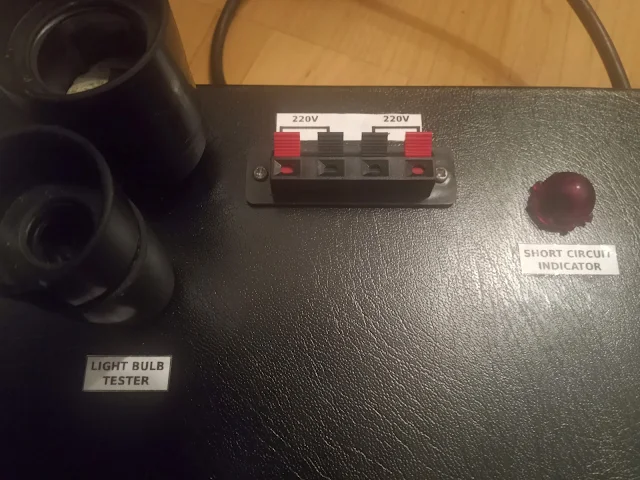
The speaker spring connector is there for testing transformers.
The 3 wires enters in a socket extension through a hole beneath it. After removing the socket cover I have added some self tapping screws to fix it on the box, then to be able to screw the socket cover back I drill 4 10mm holes under the socket where the screws are.
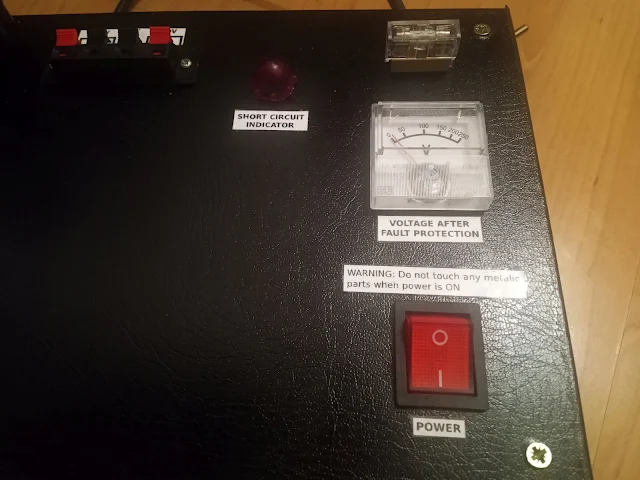
The voltmeter I had is a cheap DC voltmeter. Ideally you would use an AC one in this case but a DC one will work too using a Full Bridge Rectifier. The measured voltage will be lower but the absolute voltage was not important for me, instead I'm more interested to know the relative voltage. For example if nothing is connected and you see ~200V and then when connecting a load the voltage drops too much that indicates that the incandescent bulb must be of higher wattage type. If the voltage drops to zero that could indicate a short circuit.
To see if the incandescent light bulbs are lit in case of a short circuit I have added a 14mm hole on which I have mounted an old red bulb cover found in my scrap bins.
Because I am the kind of guy who fixes LED bulbs, I have also included two sizes of light bulb sockets (E27 and E14) to test the light bulbs.
And here are some pics with the unit
Make sure that the incandescent bulb(s) don't stay lit for a long time when the box is closed because that could melt the wires if they are touching the bulb.


Thanks! very neat and clear setup! 👍👍
ReplyDelete