Saturday, June 10, 2023

Breadboard Development Board for AVR microcontrollers | Breaduino

A development board is an essential tool when working with projects that involve a microcontroller and most of the time you will also need a breadboard and a power supply. So why not combining all these in a single product?

Meet Breaduino - a custom development board build around ATmega328PB microcontroller. If you are a beginner in electronics or microcontrollers, building a development board is not only rewarding but also educational.

Breadboard Development Board for AVR microcontrollers | Breaduino

The Breaduino dev board is designed to be used with two breadboards where it outputs three voltages: 12V, 5V and 3.3V. It includes a TFT display, micro SD card socket, input current measurement and a rotary encoder for user interaction. On the right side of the case is space for a small logic analyzer and/or a 9V battery. All these are optional modules. Even the breadboard is optional so the board can be used standalone. Since this is a customizable board it can be modified to fit your needs.

Breadboard Development Board for AVR microcontrollers | Breaduino

Sunday, August 28, 2022

IR remote control library for AVR microcontrollers

This library can be used for sending or receiving remote controller codes using a microcontroller. The supported protocols at the moment are NEC and RC-5 since these are the most commonly used.

The IR library is very easy to use and it needs a 16-bit timer for both sending and receiving. Timer 1 is used for this purpose. Before diving into the code, let's see how a remote controller works and take a closer look at their protocols.


Contents


How a remote controller works

A remote control is using optical communication to send wireless data to a receiver device. For this purpose, the infrared light was chosen. The data is transmitted on top of a carrier frequency that is usually 38kHz. There are many schemes of encoding the data because there are many manufacturers of consumer products. The most commonly used protocols are NEC, RC-5, RC-6, Sony. 

Sunday, August 7, 2022

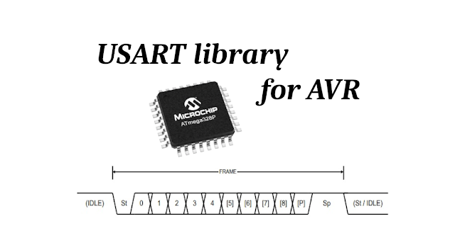
UART library for AVR microcontrollers using interrupts

This is a UART library that is made for AVR microcontrollers that can be used for serial communications.

UART is a type of serial interface, as opposed to a parallel interface. A parallel interface can work at higher speeds but the disadvantage is that it needs multiple input/output lines. Other examples of serial interfaces are SPI and I2C.

UART library for AVR microcontrollers using interrupts

Features

  • Custom Baud rate
  • Asynchronous or synchronous modes
  • Supports serial frames with 5, 6, 7, 8, or 9 data bits
  • Odd, even or no parity
  • Error detection
  • Multi-processor communication mode used to address multiple devices on the same serial bus
  • Double speed asynchronous communication mode

Thursday, August 4, 2022

Tutorial on how to program an AVR ATmega328PB microcontroller using Atmel Studio and a bootloader

In this tutorial you will be learning how to use Microchip Studio (previously known as Atmel Studio) to program an AVR microcontroller over UART using the Optiboot bootloader. The hardware necessary is very inexpensive. All you need is an ISP (In System Programming) module such as USBTinyISP (around 3$) and an USB to Serial adapter that is around the same price and you can even build it yourself if you wish.

Monday, July 25, 2022

Library for MCP4725 DAC for AVR microcontrollers

The MCP4725 is a low-power, high accuracy, single channel, 12-bit buffered voltage output Digital-to-Analog Convertor (DAC) with non-volatile memory (EEPROM). Its on-board precision output amplifier allows it to achieve rail-to-rail analog output swing. The advantage of this DAC is the A0 pin that can be used to control multiple DACs by changing their address (more on that later).

This DAC library also includes an I2C driver that is needed by the AVR to communicate with the MCP4725.

Library for MCP4725 DAC for AVR microcontrollers

Contents

  1. Pin Descriptions
  2. Wiring up one or multiple DACs
  3. MCP4725 Characteristics
  4. Code Example
  5. Using the MCP4725 library
  6. Download


1. Pin Descriptions


MCP4725 DAC pin description

MCP4725 pins

Wednesday, July 13, 2022

SD card tutorial - Interfacing an SD card with a microcontroller over SPI (part 2 of 2)

This is part 2 of the tutorial on SD card specifications. In part 1 of the tutorial we made functions necessary for SPI communication and card initialization in SPI mode. At the end of this second part you should be able to read and write an SD card.

Contents

5. Reading/Writing Data Blocks

5.1 Block Length

5.2 CMD17 – Reading a Single Block

5.2.1 Read Errors

5.3 CMD24 – Writing a Single Block

6. Conclusion or Confusion

7. Links 


SD card tutorial - Interfacing an SD card with a microcontroller over SPI (part 2 of 2)


5. Reading/Writing Data Blocks

5.1 Block Length

Block length can be set in Standard Capacity SD cards using CMD16 (SET_BLOCKLEN) however for SDHC and SDXC cards, the block length is always set to 512 bytes. Since nowadays most if not all cards are of high capacity type, we will only consider the latter in this tutorial.

SD card tutorial - Interfacing an SD card with a microcontroller over SPI (part 1 of 2)

This is a two-part series tutorial about the SD protocol used by SD flash memory cards.

Personally I learn better using practical examples instead of abstract data, and for this reason I have constructed this tutorial as a step by step with practical code examples written in C language, that can be followed by anyone with basic programming skills and knowledge on how to use a microcontroller. Although I am using an ATmega328P in this tutorial, the concepts extend to any microcontroller.

In case you just need a library to read/write a memory card, you can find one here: https://www.programming-electronics-diy.xyz/2022/07/sd-memory-card-library-for-avr.html. This tutorial will help in understanding the low-level interactions between a microcontroller and a memory card but it will not be enough to use an SD card in a practical way. Apart from an SD card driver, that is the code described in this article, you will also need a file system driver such as FAT16 or FAT32 in order to read or write files. Writing and reading data to a memory card without a file system, is like using a large EEPROM.

Contents

1. General Description

1.1 Bus Mode and Clock Speed

1.2 Read/Write Mode Selection

2. SD Card Hardware Interface

2.1 microSD Card Schematic SPI Interface

3. SPI Setup

4. Card Initialization

4.1 Power Up Sequence

4.2 Sending Commands

4.3 Initialization Flow

4.4 CMD0

4.5 Response R1

4.6 CMD8

4.7 Response R7

4.9 CMD58

4.10 Response R3

4.11 ACMD41 & CMD55

5. Reading/Writing Data Blocks

5.1 Block Length

5.2 CMD17 – Reading a Single Block

5.2.1 Read Errors

5.3 CMD24 – Writing a Single Block

6. Links


SD card tutorial - Interfacing an SD card with a microcontroller over SPI (part 1 of 2)

1. General Description

The Secure Digital (SD) Card was developed by the SD Association (SDA) as an improvement over MMCs. The SD Card specifications were originally defined by MEI (Matsushita Electric Company), Toshiba Corporation and SanDisk Corporation. Currently, the specifications are controlled by the Secure Digital Association (SDA).

In addition to the mass storage specific flash memory chip, the SD Card includes an on-card intelligent controller which manages interface protocols, security algorithms for copyright protection, data storage and retrieval, as well as Error Correction Code (ECC) algorithms, defect handling and diagnostics, power management and clock control.