In part 1 on How to make a POV display we talked about the hardware and schematic. In this part 2 we will dive in how the code works and why the POV (Persistence Of Vision) display is so cool and fun to play with.
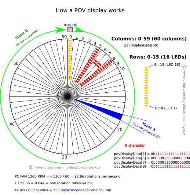
Looking at the example in the above figure we want to display the letter "H" starting from column 5.
First we need to measure the time it takes for the PC fan to make a full rotation. For this we will use a Hall effect sensor and a magnet.When the Hall effect sensor on the board passes above the magnet an interrupt will be triggered that will start Timer 0. Next time the display makes a full rotation, the magnet will trigger the interrupt again and Timer 0 holds now the time it takes to make a full rotation (44ms in this example).
Say a PC fan has 1360 RPM divided by 60 = 22.66 rotations per second.
1 / 22.66 = 0.044 seconds or 44 milliseconds for one rotation.
To find out after how much time the next column can be displayed, the time it takes for a full rotation is divided by the number of columns (60 in this example).
time_per_column = one_rotation_time / number_of_columns
time_per_column = 44ms / 240 = 183 microseconds per column for 240 columns
time_per_column = 44ms / 120 = 366 microseconds per column for 120 columns
time_per_column = 44ms / 60 = 733 microseconds per column for 60 columns
Notice how increasing the number of columns decreases the time available for one column. More columns gives a better resolution but the microcontroller must be fast enough to finish the code in that time. Number of columns can be changed in software.
Timer 2 is set to trigger interrupts every 733 microseconds. On each interrupt the 16 leds are updated based on what is to be displayed on the active column. The array povDisplayData[] is used for this. Looking at the above figure again, if the active column is 4, all leds would be off because povDisplayData[4] would be all 0's. On the next column 5 all the leds are on to display the first part of the "H" character. On columns 6 and 7 only two leds are on. What leds are on depends on how you want to draw the characters.
Turning the leds on and off with as less code as possible is not as easy as it should be. If all leds would be on a single port this would be achieved simply like this:
PORT0 = povDisplayData[active_column];
But when the leds are located on multiple ports the code becomes a bit tricky. I have used some bitwise operations and bitmasks for this. Switch case takes 10 times longer and if/else conditions even longer.
Connecting the app to POV display device
On first use the device will create an wireless access point with SSID: POV Display and KEY: ESP826608. With a wireless device connect to this access point then using the Android app access Router Credentials page under the menu. Here you need to pass the credentials of your router for the ESP8266 to connect to the router. This step is only necessary once and after this the credentials are saved inside ESP8266 flash memory.
* a flashing blue light indicates the device is waiting for router credentials
Download
This zip file contains main code and dependency libraries:
- POV Display - EFM8BB31F32_main.c
- uart.h
- ESP8266.h
- Flash.h
- globals.h
- delay.h
If you want to know how to program an EFM8 microcontroller visit this link https://www.programming-electronics-diy.xyz/2018/03/cheap-and-powerful-50-cents-microcontroller.html
However you don't need Simplicity Studio for that. For uploading the code I have also included:
- POV Display - EFM8BB31F32.efm8
This is the compiled file that needs to be uploaded on the microcontroller using an executable provided by the Silicon Labs
- efm8load.exe
And a bat file for uploading on COM3. This can be edited.
- 2 - Bootload Record Downloader.bat
The bat file contains:
@echo Downloading bootload record using COM3
@efm8load.exe -p COM3 -t "POV Display - EFM8BB31F32.efm8"
@pause


Hello, sorry what do you mean when you said "set Timer 2 to trigger an ISR", what is an ISR?
ReplyDeleteHi. An ISR means Interrupt Service Routine and is like a function that interrupts the main code when an event occurs. In this case is a timer event. It can be an overflow or when the timer counts to a certain number then an interrupt is generated and the code inside the interrupt is executed. This is the ISR for timer 2:
DeleteSI_INTERRUPT (TIMER2_ISR, TIMER2_IRQn){
// code goes here
}